Grips and Fixtures for TensileMill Universal Testing Machines

Grips and Fixtures for TensileMill Universal Testing Machines


Grips and Fixtures

Grips and fixtures are essential components used with universal testing machines (UTMs). They hold the specimen in place and transfer the applied load during tensile, compression, flexural, shear, peel, and puncture tests. Proper gripping helps maintain specimen geometry and supports testing according to ASTM, ISO, and other relevant standards.

TensileMill CNC provides a selection of grips and fixtures for both electromechanical and servo-hydraulic UTMs. Each configuration is matched to the material and test method, covering applications from films and elastomers to metals and composite laminates. Options include wedge grips for high-strength metals, pneumatic grips for frequent test cycles, and flexural fixtures for 3-point and 4-point bending setups.

The available designs accommodate different specimen shapes and sizes. Many models support interchangeable jaw faces, such as smooth, serrated, or rubber-coated surfaces. Certain mechanisms increase clamping force with rising load, helping the specimen stay secured without crushing or slipping during testing.

Selecting appropriate grips and fixtures allows the UTM to function as a versatile testing platform for research, production, and standards-based quality control. These accessories are used in test methods such as ASTM E8 for tensile properties, ASTM D695 for compression, and ISO 178 for flexural evaluation, supporting consistent measurements under controlled testing conditions.

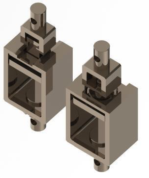
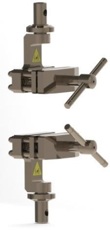
Side Action Tensile Grips for General Clamping Applications


Grips and Fixtures

Side action tensile grips are mechanical clamps used for tensile testing of plastics, metals, textiles, rubber, and composite specimens. These grips apply lateral pressure through two jaws that are tightened manually with a screw or lever mechanism. This method allows for controlled clamping without leaving marks on the specimen's surface.

These grips are commonly used in medium-load testing environments such as quality control labs and research facilities. Interchangeable jaw faces, including smooth, serrated, and rubber-coated options, help match the clamping surface to the material being tested, which supports consistent gripping and reduces the chance of specimen movement during the test.

Side action grips are practical for standardized tensile testing where a stable holding force and straightforward setup are needed. They offer a simple and economical clamping method without the additional components required for pneumatic or hydraulic gripping systems.

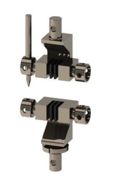
Snubbing Grips for Wire and Cable Tensile Testing


Grips and Fixtures

Snubbing grips, also known as capstan grips, are used for tensile testing of wires, ropes, fiber bundles, and electrical cables that tend to slip during loading. The specimen is wrapped around a curved mandrel or capstan to create friction along its length. This distributes the load and avoids concentrating stress at a single point.

This setup makes it possible to accurately measure the tensile strength of materials like steel cables, braided conductors, and reinforced wire products. The free end of the specimen is commonly secured with a clamp or wedge insert to maintain stable loading throughout the test.

Snubbing grips are used in cable manufacturing, laboratory testing, and quality control for structural and infrastructure applications. They are selected for specimens that require secure holding without surface damage and are suitable for testing procedures performed under ASTM, ISO, and related standards.

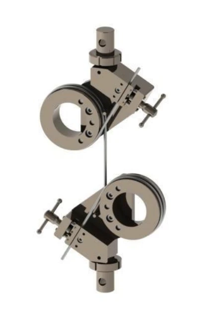
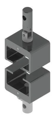
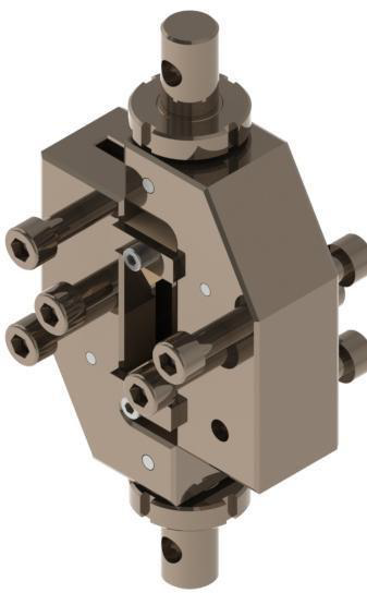
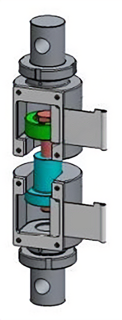
Self-Tightening Grips for Deformable and Elastic Materials


Grips and Fixtures

Self-tightening grips increase clamping force as tensile load is applied. They are used for specimens that stretch or reduce in thickness during testing, such as elastomers, thin plastics, foams, textiles, and biomedical materials. The gripping mechanism adapts to changes in specimen dimensions without requiring manual adjustment during the test.

Common configurations include scissor-type grips, eccentric cam grips, and lever-actuated jaw systems. As the load rises, the jaw movement provides additional holding force, which helps maintain contact with the specimen and limits surface slipping at higher elongation levels.

These grips are used in quality control labs, textile and rubber production, and research settings, performing standardized tensile tests on soft or flexible materials. They support consistent clamping conditions throughout the loading cycle and are practical for materials with low friction or high elongation behavior.

Eccentric Roller Grips for Thin and Flexible Samples


Grips and Fixtures

Eccentric roller grips are self-tightening fixtures used for tensile testing of thin films, rubber sheets, flexible plastics, and other low-strength materials. The design uses an off-center roller that presses the specimen against a fixed surface. As the tensile load increases, the roller rotates and adds clamping force.

This mechanism maintains contact with the specimen as it elongates or reduces in thickness, helping prevent slipping or tearing during the test. To support delicate materials, the gripping surfaces are commonly coated with rubber or other non-marking materials.

Eccentric roller grips are used in research labs, quality control environments, and manufacturing lines that work with soft or flexible specimens. Their lever-operated design allows quick specimen setup while maintaining steady clamping throughout loading. These grips are compatible with ASTM and ISO test methods for films, elastomers, and similar materials.

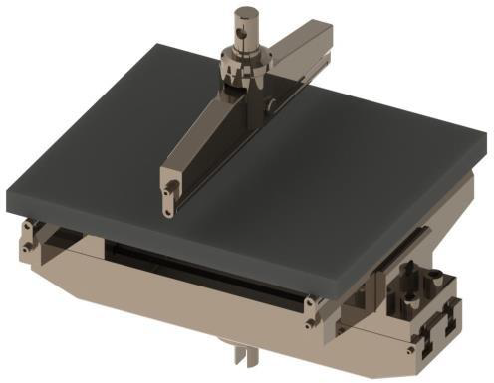
Bending Fixtures for Standard 3-Point Flexural Testing


Grips and Fixtures

Bending fixtures, also referred to as flexural test fixtures, are used with universal testing machines to carry out 3-point and 4-point bend tests. These tests are performed to evaluate flexural strength, modulus of elasticity, and related bending properties in plastics, metals, wood, and composite materials.

A typical setup includes two lower support anvils and one or two upper loading noses or rollers. The span length can be adjusted to suit the specimen dimensions and geometry. These fixtures are commonly applied in testing procedures such as ASTM D790 for plastics and ASTM C393 for sandwich panel structures. The fixture layout supports stable alignment and reduces unwanted friction during loading.

Bending fixtures are used in manufacturing, research, and laboratory environments to create controlled flexural loading conditions. They are produced from rigid steel or aluminum to maintain shape under load, helping the applied force transfer directly through the specimen during the test.

Compression Fixtures for Axial Load Testing of Rigid Specimens


Grips and Fixtures

Compression fixtures are used with universal testing machines to apply axial compressive loads in a controlled and aligned setup. The standard configuration uses flat compression platens made from precision-machined steel, which support even force transfer across the specimen surface.

For higher accuracy or high-force applications, one of the platens may include a spherical seat to help align the loading surface with the specimen and reduce off-axis loading. Additional fixture formats, such as compression cages or four-post assemblies, are used for testing larger specimens, including foam blocks, packaging materials, and structural components, where specimen stability during loading is important.

These fixtures are produced in various sizes and capacities for use with plastics (ASTM D695), concrete cubes, metals, composites, and paperboard materials. They are commonly used in materials testing laboratories, construction quality control, and packaging evaluation to support consistent compressive strength measurements.

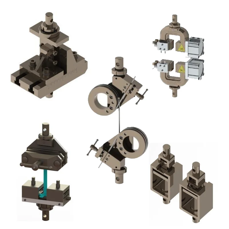
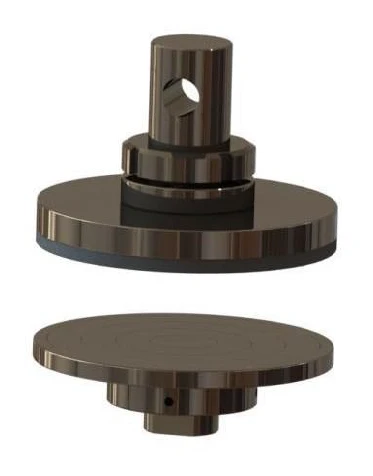
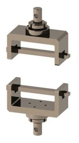
Shoulder Grip Fixtures for Pull-Off and Component Strength Testing


Grips and Fixtures

Shoulder grip fixtures are used for testing specimens that have an enlarged head, flange, or formed end that cannot be held with standard jaw clamps. These fixtures support pull-off, push-out, and component strength evaluations where force must be applied through the shoulder of the part to reflect how it is used in service.

Typical applications include bolt head retention tests, cable termination pull tests, syringe plunger withdrawal tests, mechanical anchors, buttons, bottle caps, and fastener hold strength assessments. The specimen is supported by a recessed ledge or collar, while the axial load is applied from the testing machine.

These fixtures are used in medical device testing, automotive and mechanical component assessment, packaging evaluation, and construction anchoring validation. They help distribute the load across the shoulder region to reduce bending and maintain alignment. The fixtures are produced in multiple sizes and configurations to meet ASTM, ISO, and related test procedures.

Pneumatic Clamping Grips for Consistent Specimen Holding


Grips and Fixtures

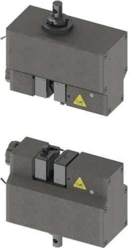
Pneumatic grips use controlled air pressure to apply stable and repeatable clamping force to the specimen. They are operated by a hand switch or foot pedal, and the integrated air cylinders close the jaws with adjustable pressure that can be set according to the material being tested. This helps maintain surface integrity while holding the specimen securely during tensile loading.

These grips are commonly used for rubber, plastics, textiles, and other flexible or soft materials where controlled clamping is important. The applied pressure can be adjusted to help limit crushing or slipping during standardized tensile procedures.

Due to their quick operation, pneumatic grips are used in high-throughput testing environments such as quality control labs and production settings. Variants including pneumatic side action designs are suited for mid-range test forces, often up to 20 kN, and support centered specimen alignment during loading.

Pneumatic grips are compatible with testing performed under ASTM, ISO, and similar standards, making them suitable for routine testing and development work across materials that benefit from adjustable, repeatable clamping conditions.

Wedge Clamping Grips for High-Strength Metal and Composite Specimens


Grips and Fixtures

Wedge clamping grips use a wedge-based jaw mechanism that increases holding force as the tensile load rises. The internal wedge slides against serrated or knurled jaw surfaces, which continue to tighten on the specimen during loading.

These grips are used for high-strength materials such as structural metals and composite laminates, where high load capacity and firm holding are required. They are produced in manual and hydraulic versions and support force levels ranging from moderate test loads to capacities exceeding 500 kN.

Wedge clamping grips are used in materials testing laboratories, aerospace and automotive component evaluation, and research settings where standardized tensile tests are performed. They support testing practices such as ASTM E8 and ISO 6892 by maintaining axial load alignment and steady clamping conditions for hard, rigid specimens.

3-Point and 4-Point Bending Fixtures for Uniform Moment Flexural Testing


Grips and Fixtures

3-point and 4-point flexural fixtures are used with universal testing machines to evaluate the bending properties of materials under controlled loading conditions. In a 4-point configuration, two loading rollers apply force at equal distances from the supports, producing a constant moment region between the load points. This method is used to measure flexural modulus and deformation behavior with as little effect from shear loading in the middle section as possible.

These fixtures are suitable for brittle materials, plastics, composites, and concrete beams where even stress distribution is important. Common reference standards include ASTM D6272 for plastics and ASTM C78 for concrete flexural testing.

The fixture assembly includes two upper loading rollers and two adjustable lower supports. The support span can be set to match specimen size and testing requirements. These flexural fixtures are used in construction material testing, composite manufacturing, and research environments to study bending performance and fracture characteristics under stable and repeatable loading conditions.

Grips and Fixtures for Tensile, Shear, and Flexural Testing of Wood Specimens


Grips and Fixtures

Wood testing grips and fixtures are designed to work with the directional structure and variable density of wood and timber specimens. These setups are used for mechanical tests referenced in standards such as ASTM D143 and ASTM D4761, including tensile, shear, compression, nail and screw withdrawal, and flexural evaluations.

For tensile testing parallel to the grain, flat or serrated jaw grips or shoulder-type clamps are used to hold dogbone specimens without crushing the loaded section. For tests that are perpendicular to the grain, fixtures with bonded support plates are used to keep the specimen stable. Block shear fixtures are used to measure shear strength along the grain under tension or compression. Nail and screw withdrawal fixtures apply axial force to fasteners embedded in wood to determine withdrawal resistance.

Compression testing is performed using large-area or self-aligning platens to support uniform load applications. Flexural properties such as modulus of rupture and modulus of elasticity are measured using 3-point or 4-point bending fixtures for lumber, beams, and engineered wood products.

These fixtures are used in wood products manufacturing, construction materials testing, and furniture and fastener development. Their designs help maintain proper specimen support and load transfer while accounting for material variability typical of natural wood.

Composite Testing Grips and Fixtures for Tensile, Shear, and Delamination Evaluation


Grips and Fixtures

Composite testing grips and fixtures are designed for the mechanical testing of carbon fiber reinforced polymers, fiberglass laminates, and other layered composite materials. Because composites can fail prematurely from gripping pressure or misalignment, the fixtures are configured to support controlled load application across the intended failure region.

For tensile testing, hydraulic wedge grips with surface-treated jaws are used to maintain hold on composite laminates without crushing or slipping. Compression testing commonly uses Combined Loading Compression (CLC) and IITRI-style fixtures, where side supports or end tabs help produce the correct failure mode.

Interlaminar and in-plane shear evaluations are performed using short-beam shear fixtures (ASTM D2344), Iosipescu shear fixtures (ASTM D5379), and rail shear devices (ASTM D7078). Delamination and fracture toughness assessments include double cantilever beam setups for Mode I (ASTM D5528) and end-notch or mixed-mode bending fixtures for Mode II.

Additional configurations include picture frame fixtures and bias extensometer arrangements for fabric in-plane shear, as well as floating roller peel (ASTM D3167) and climbing drum peel (ASTM D1781) fixtures for adhesive and bonded laminate peeling tests.

Specialized Fixtures and Grips for Tear, Peel, and Puncture Testing


Grips and Fixtures

Specialized grips and fixtures are used for tear, peel, puncture, pull-through, buckle, and other non-standard mechanical tests where conventional tensile or compression grips are not suitable. These configurations are designed to match specific material behaviors and specimen shapes.

Peel testing setups include 90-degree peel fixtures and climbing drum peel fixtures for evaluating bond strength in adhesives, laminates, tapes, and layered assemblies. Tear testing grips are used for plastic films, fabrics, and other flexible sheet materials to study tear propagation. Puncture testing fixtures include systems for geomembranes under ASTM D4833 and ball burst devices for textiles in accordance with ASTM D3787.

Additional configurations include eyelet pull-through grips, buckle testing fixtures, and custom shear fixtures such as adhesive lap joint setups following ASTM D4501. These fixtures are used in packaging development, textile and film manufacturing, materials testing laboratories, and product engineering environments that require controlled testing beyond standard tensile or compression methods.

TestStar® Series Grips and Fixtures for Hydraulic UTM Systems


Grips and Fixtures

TestStar® series grips and fixtures are designed for use with TestStar® hydraulic universal testing machines. These accessories fit the machine's mounting points, can handle the right amount of force, and help apply loads steadily during strong pulling, pushing, and bending tests.

The series has different types of grips and fixtures, including capstan-style grips for wires and cables, side action grips for general pulling tests, wedge clamping grips for strong metals and composite materials, and fixtures for testing plastics, metals, and composites under compression and bending. 3-point bending assemblies are available for structural flexural evaluation.

TestStar® grips and fixtures are used in materials testing laboratories, industrial production facilities, and research environments where larger specimens or elevated load requirements are common. Hydraulic configurations are available for high-capacity loading and continuous test operation.

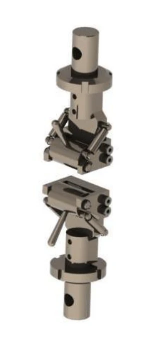
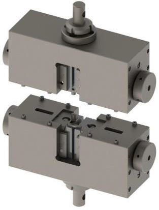
Dual-Action Hydraulic Wedge Grips for High-Force Tensile Testing


Grips and Fixtures

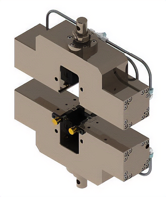
Dual-action hydraulic wedge grips are used for high-capacity tensile testing where stable clamping and controlled jaw movement are required. In side-action mode, the jaws close from both sides under hydraulic pressure, providing even clamping across flat or wide specimens. This helps maintain alignment during loading.

In wedge-action mode, angled jaw slides increase gripping force as the tensile load rises. This configuration supports large metal specimens, steel rods, fasteners, and other high-strength materials used in structural or industrial applications. The hydraulic system allows pressure to be set before the test, supporting consistent specimen engagement.

These grips are used with servo-hydraulic universal testing machines in construction materials labs, metal processing facilities, and industrial manufacturing environments. Their heavy-duty construction supports high load capacities, making them suitable for testing rebar, bolts, and structural metals under elevated tensile forces.

Threaded Fastener Grips for Bolt and Nut Tensile Testing


Grips and Fixtures

Threaded fastener grips are used for axial tension testing of bolts, screws, studs, and nuts. Instead of clamping the specimen externally, these fixtures use threaded adapters or holders that engage directly with the part’s threads. This setup applies load through the fastener in a way that reflects how it is used in service.

These grips are used to evaluate tensile strength, yield characteristics, and proof load requirements for fasteners in accordance with standards such as ASTM F606. In proof load testing, a nut is installed on a hardened threaded mandrel and loaded to a specified tension to confirm thread integrity and load-bearing capability without failure. Interchangeable threaded inserts are available to match different thread sizes.

Threaded fastener grips are used in automotive, aerospace, construction, and mechanical testing environments. They are manufactured from high-strength steel to support elevated load capacities, often exceeding 100 kN. These grips provide consistent test alignment and measurable data for quality control and certification of structural and mechanical fasteners.

Hydraulic UTM Grips and Fixtures for High-Force Tensile Testing


Grips and Fixtures

Hydraulic UTM grips and fixtures are used in high-force tensile testing to ensure that the materials are held securely and that the force is applied accurately. This category includes hydraulic side action grips and hydraulic wedge grips for pulling metal coupons, bars, rods, and other structural specimens. It also includes tensile shear fixtures, which apply tension to joints or bonded assemblies to evaluate shear strength, and proof load fixtures for fastener testing.

A typical nut-proof load setup uses a hardened threaded mandrel to hold the nut while axial load is applied to confirm that the threads can withstand the specified tension without stripping. These fixtures are built to support very high forces, as large fasteners and structural components may require testing at loads measured in hundreds of kilonewtons. Many hydraulic grips also incorporate interchangeable jaw inserts and reinforced clamping surfaces to support different specimen geometries and diameters.

The purpose of these fixtures is to apply high tensile forces with controlled alignment. Maintaining vertical load alignment is critical in hydraulic systems, since off-axis loading at high force can introduce bending stresses. With the right grips and setups for a hydraulic frame, users can carry out regular tests like ASTM E8 for metals and ASTM A370 for rebar, along with proof load tests for fasteners and tension-based shear tests. Each fixture is made to meet the specific test standards and works with powerful load cells and hydraulic systems.

What Starting Blank Size Fits the Standard Triple Sample Fixture?

Start with blanks that are close to the final specimen thickness to minimize roughing passes and keep dimensional accuracy high. The standard Triple Sample Fixture includes three independent clamps, and each clamp comfortably accommodates blank widths up to 1.5 in (38 mm). Keeping thickness near net size cuts cycle time, lowers cutter load, and helps maintain parallelism and gauge geometry during CNC machining. If your stock is wider than 1.5 in (38 mm), our engineering group can propose alternatives such as custom jaws, different workholding layouts, or process adjustments suited to your material and throughput goals. For challenging alloys or mill scale, you may also discuss tooling selection, feeds and speeds, and clamping strategy to balance surface finish, burr control, and tool life. If you would like to compare available workholding and compatible accessories, you can review options on the Grips and Fixtures page.

What Maximum Temperature Can Tensile Grips Withstand on a Universal Testing Machine?

TensileMill CNC supplies standard and specialty grips rated for high-temperature testing up to 1,922°F (1,050°C). The usable limit depends on the specific grip style, jaw material, and the thermal accessories integrated with your chamber or furnace. For sustained operation near the upper range, select high-temperature wedge or side-action grips built from heat-resistant alloys and pair them with ceramic, serrated, or smooth jaw faces matched to the specimen surface. Thermal shields, extension rods, and insulation help keep the crosshead and load cell outside the hot zone. Pneumatic designs may require high-temperature seals and remote actuation lines located away from the heat source. Setups for elevated temperature testing benefit from careful alignment to maintain axial load paths, correct jaw face selection to limit slippage or marking, and verification that the grip capacity and specimen geometry remain compatible at temperature. For long soaks or repeated cycles, schedule periodic inspection of jaws and fasteners to maintain consistent clamping performance. If you would like to review high-temperature grip options, jaw materials, and compatible accessories, you can explore the Grips and Fixtures for TensileMill Universal Testing Machines page for details on the equipment page.

Will Future TensileMill CNC Accessories Work With Existing or Older Machines?

Yes. New accessories are developed with backward compatibility in mind, so they integrate with current systems and many legacy TensileMill CNC machines and universal testing frames. Our design approach favors common mounting patterns, controller interfaces, and standard UTM connections, and we support legacy fleets with adapter kits when a direct fit is not available. For testing labs, this means new grips, fixtures, jaw faces, and polishing or cutting tools can often drop into existing workflows without changing procedures tied to ASTM E8 or ISO 527 when those standards apply to your program. For machining-based specimen preparation, holders, collets, and base fixtures are matched to prior spindle and fixturing setups, and software updates keep the operator interface familiar. If your equipment is older or customized, our team can validate fitment before shipment. Sending the model and serial number, photos of the mounting or spindle interface, and your current software revision lets us confirm compatibility and recommend any adapters or simple field updates. This strategy helps extend the service life of installed equipment while maintaining specimen quality and throughput. If you would like to review compatible tooling, fixtures, and replacement parts by category, you can explore details on the Consumables and Spare Parts page.

What Are the Main Types of Bend Tests in Materials Testing?

Yes. Common bend methods used in mechanical testing include Guided Bend, Semi-Guided Bend, Free Bend, and bend-based Fracture Toughness evaluations. In a Guided Bend, the specimen is supported at both ends and forced over a die or plunger so it wraps into a U shape, which is frequently used for weld coupons under codes such as AWS D1.1 and general metallic bend procedures such as ASTM E290. A Semi-Guided Bend uses adjustable supports or a mandrel to target a specific bend radius or angle, making it useful when you need to compare ductility at a controlled curvature. A Free Bend brings the ends toward each other without a central loading nose, so results are more sensitive to specimen geometry and surface friction; labs often standardize span, thickness, and finish to improve repeatability. For Fracture Toughness with bend geometry, a precracked specimen, often a single-edge bend SE(B), is loaded opposite the crack mouth to obtain parameters such as J or K under standards like ASTM E1820. The best choice depends on whether you are qualifying weld soundness, trending ductility, or characterizing crack-growth resistance. If you would like to discuss bend fixtures or UTM options for your lab, you can connect with our team on the Contact Us page.

Which Grips and Fixtures Are Available for TM-EML Series Universal Testing Machines?

TensileMill CNC offers a broad catalog of grips and fixtures for TM-EML Series load frames to support tension, compression, flexure, peel, tear, puncture, and fastener testing across metals, plastics, elastomers, films, cables, and composites. Common options include wedge grips for flat and round metallic specimens used with ASTM E8 and ISO 6892 methods, pneumatic grips for rapid, repeatable clamping of soft or flexible materials, and side-action grips with interchangeable jaw faces for general lab workflows. Self-tightening and eccentric roller styles address wires, thin films, and deformable specimens. Flexural fixtures are available in 3-point and 4-point configurations for plastics and laminates per ASTM D790 and ISO 178, while compression platens support axial loading per ASTM D695. Threaded adapters and proof fixtures cover bolts, studs, and nuts per ASTM F606, and specialized peel, tear, and puncture fixtures serve films, laminates, bonded assemblies, and packaging. All accessories interface directly with the TM-EML crosshead and load cell to promote coaxial loading, stable clamping, and repeatable results. Quick-change adapters, a wide range of jaw surfaces, and optional pneumatic regulators streamline throughput, and fixtures integrate cleanly with the system software for limit settings and method templates. Application-specific jaws and custom fixtures can be supplied to match specimen geometry or surface finish requirements. If you would like to compare available jaws, adapters, and fixture styles for your TM-EML frame, you can review options on the Grips and Fixtures page.

What Utility Requirements Apply to TM-EML Universal Testing Machines With Pneumatic Grips or Environmental Chambers?

TM-EML load frames operate on electrical power only. The base machine does not need compressed air or external ventilation for motion control, data acquisition, or routine testing. Air and ventilation are required only for certain accessories. Pneumatic grips run from a typical laboratory air line at 80 to 100 psi (5.5 to 7 bar). If plant air is not available, a compact oil-free compressor can be used, and clean, dry air is recommended for consistent clamping performance. Environmental chambers carry their own utility needs. Depending on the model, a separate electrical connection and, in some cases, an exhaust pathway may be specified by the chamber supplier. These utilities belong to the chamber, not the TM-EML frame. If you plan to add pneumatic grips, a temperature chamber, or other powered accessories, share your accessory list and test range with our team so we can confirm utilities for your exact configuration. If you would like to review frame capabilities and compatible accessories, you can learn more on the TM-EML Series C UTM equipment page.

Which Alignment Tools and Procedures Prepare TM-EML Series UTMs for NADCAP or Similar Accreditation?

TM-EML testing frames support formal alignment workflows used for NADCAP and comparable audit programs. Operators can verify axiality with alignment fixtures compatible with ASTM E1012 and with ISO-aligned practices. These tools measure load-string symmetry, bending strain, and force distribution so you can adjust grips, adapters, and crosshead centering before a calibration visit. GenTest software guides stepped loading and captures alignment data, then generates a traceable report for auditors. In practice, select an alignment bar or multi-gage fixture that matches your grip type, install it between the upper and lower adapters, and zero the sensors. Run a controlled tension profile in GenTest, add compression if required by your audit scope, and watch live axiality and bending indicators. If readings show eccentricity, correct grip parallelism, change or reface worn jaw faces, confirm adapter concentricity, and recenter the crosshead, then repeat the sequence until bending falls within your program limits. Save the GenTest protocol with operator ID, instrument serial numbers, and calibration references to document the alignment state. Our team can help match the correct alignment fixture to your frame and jaw style for a smooth audit. If you would like to review compatibility and reporting features, you can read more on the TM-EML Series C UTM product page.

What Comes Standard With a TM-EML Series Universal Testing Machine, and Which Options Are Most Popular?

Each TM-EML order ships ready to test with the load frame, a closed-loop AC servo controller, a precision load cell matched to the selected capacity, and the GenTest software package. Basic tensile grips or compression platens are supplied according to the methods specified on the order, and the machine includes safety features such as an emergency-stop circuit, travel limit switches, and motor protection. If you would like to compare capacities and accessory choices, you can review technical details on the TM-EML Series C UTM page.

How Does the TM-EML Series A UTM Protect Thin, Soft, or Fragile Specimens During Gripping and Preload?

The TM-EML Series A applies very low crosshead speeds, programmable preload ramps, and high-resolution, low-capacity load cells to avoid overstressing delicate materials during initial contact and alignment. The control loop stabilizes force at first touch so thin films, textiles, soft polymers, and foams are clamped without tearing or early deformation. Operators can start with a slow approach, hold a small preload for alignment, then transition into the test method. Pressure-regulated pneumatic grips or soft-faced inserts distribute clamping force evenly and reduce local stress peaks; smooth, rubberized, or light-serrated jaw faces can be selected for compliant surfaces. Force feedback at low ranges maintains a steady, repeatable preload and prevents spikes during specimen seating. This workflow supports fragile-specimen methods such as ASTM D882 for thin plastic sheeting, ASTM D5035 for textiles, and ISO 527-3 for plastic films, helping labs capture stable data while protecting samples and minimizing regrips. If delicate materials are part of your workflow, you can review preload control, gripping options, and other specifications on the TM-EML Series A UTM product page.

How Fast Is Changeover for Grips, Fixtures, and Load Cells on the TM-EML Series A Universal Testing Machine?

Most grip and fixture swaps take only a few minutes. The single-column, open-front test space and quick-mount adapters let operators release the current setup, insert the next jaws or fixture, and return to testing with minimal steps. Load cells are also fast to change, because the system uses plug-and-test identification that automatically reads sensor data as soon as the cable is connected. In practice, you disengage the upper and lower adapters, remove the installed jaws or fixture, and slide in the next configuration. The accessible test area supports rapid jaw face changes for plastics or elastomers, as well as quick alignment for flexural or compression fixtures. For a load cell swap, the keyed mounting keeps the sensor centered, then the controller detects the TEDS chip, loads the stored calibration, and updates capacity limits without manual entry. A short zero and a light preload confirm readiness. This workflow helps labs move between methods such as ASTM D638 and ISO 527 with minimal downtime, keeping sample throughput steady during frequent material or geometry changes. If you would like a closer look at accessory changeover and sensor integration, you can review technical details on the TM-EML Series A UTM product page.

How Does the Pneumatic Grip Control Module Work on the TM-EML Series A UTM?

The optional pneumatic grip control module plugs into the Series A frame and lets the operator open or close pneumatic grips from panel buttons or through the GenTest software. A built-in regulator applies the programmed air pressure for the selected grip, so clamping force remains consistent from specimen to specimen. During setup, you select the desired grip action and pressure, then the module manages air delivery while the UTM runs. The control logic ties into the machine’s interlocks, which means the crosshead will not jog or start a method until the grips confirm the commanded state. This prevents premature movement, reduces specimen slippage risk, and supports repeatable workflows during batch testing. Pneumatic gripping is commonly chosen for flexible materials and frequent changeovers, including thin films, textiles, and elastomers where low to moderate clamping pressure is needed. Typical methods include ASTM D882 for films and ASTM D412 for rubber, where uniform jaw force helps produce stable results without surface damage. If you would like to see how this module integrates with the frame and software, you can review details on the TM-EML Series A Universal Testing Machine product page.

Can TM-EML Series A UTMs Integrate With External Sensors And Custom Accessories For R&D?

Yes. Series A test frames can integrate with third-party sensors and custom accessories when they communicate through the GenTest software environment or compatible controller I/O. Many labs add external displacement devices, clip-on or video extensometers, custom grips, or environmental components that either stream data to the controller or capture it on a separate data system for later correlation. When an accessory needs a specific mount or connector, it can be placed in the load string, on the crosshead, or in the base fixture area using purpose-built adapters. This approach keeps the load path aligned and preserves the frame’s control loop. During setup, match signal types and ranges to the available channels, verify grounding to avoid noise, and confirm that added fixtures do not exceed rated capacity. For parallel data capture, a shared trigger or time marker helps synchronize external measurements with force and crosshead signals. Our team can provide adapter plates, wiring pinouts, and guidance on integrating accessories so R&D workflows remain fast and repeatable. If you would like to review connectivity options in more detail, you can explore the integration notes on the TM-EML Series A UTM product page.

How Fast Can Grips, Fixtures, and Load Cells Be Changed on the TM-EML Series B UTM?

Most grip bodies and fixtures on the Series B can be swapped in a few minutes. The open-front test space and quick-mount interfaces provide direct access to the load string, so operators transition between setups with minimal tools. Load cells are also changed quickly because the sensors include TEDS digital identification, which lets the controller recognize the connected capacity automatically without manual calibration entry. In practice, changeover typically involves returning the crosshead to a safe position, unloading the frame, releasing the quick pin or threaded adapter, removing the current grip, then installing the alternate jaws or fixture and re-zeroing force. When a different load cell is plugged in, the TEDS chip prompts the software to load the stored calibration and limits, reducing input steps and cutting the chance of parameter errors. This workflow is helpful when moving from tensile grips to a three-point bend fixture for methods such as ASTM D790, or when switching to a lower-capacity sensor for thin films or wires. The result is less downtime between batches and a smoother routine for QC, R&D, and teaching labs. If you would like to review configuration options for faster changeovers, you can explore details on the TM-EML Series B Universal Testing Machine page.

How Does the Pneumatic Grip Control Module Work on the TM-EML Series C UTM and What Are the Workflow Benefits?

The optional pneumatic grip control module provides closed-loop, digital pressure regulation for the upper and lower grips on the TM-EML Series C. Operators set and monitor clamping pressure from the handheld console or directly in GenTest software, with independent channels for each grip. An integrated electronic regulator maintains the target pressure during the test, and quick-connect air ports make it straightforward to attach pneumatic side-action grips or other air-operated fixtures for tensile or compression work. For routine testing, this module improves repeatability by applying the same clamping force every time, which reduces operator-to-operator variation and helps protect delicate or compliant specimens from over-tightening. Preset profiles let labs switch materials or jaw faces without re-tuning pressure, which shortens changeovers and speeds batch throughput. Built-in safety logic ties grip actuation to machine state, so clamping remains disabled until the test space is clear and the frame is ready, helping prevent unintended jaw movement during setup. If you would like to review control options, pressure presets, and compatible pneumatic grips, you can learn more on the TM-EML Series C Universal Testing System page.

How Do I Choose the Right Grips and Fixtures for My Universal Testing Machine?

Start with the test method, specimen geometry, and expected peak load. Select a grip or fixture capacity that is at least 1.5 to 2.0 times your calculated maximum, for example a specimen expected to reach 3,000 lbf (13.3 kN) should use grips rated around 5,000 to 10,000 lbf (22.2 to 44.5 kN). Match jaw face width to the specimen, commonly 1.0 to 2.0 in (25.4 to 50.8 mm), and choose surfaces that protect the gauge section while preventing slip. Align the mechanism to the material behavior. Wedge grips suit metals under ASTM E8 or ISO 6892. Pneumatic or eccentric roller designs work well for plastics and elastomers in ASTM D638 or ISO 37 by applying controlled pressure. Capstan grips stabilize wires, cords, and textiles by wrapping to create friction. Use 3- or 4-point flexural fixtures for plastics and composites per ASTM D790, and flat or self-aligning platens for compression in ASTM D695 where parallelism is critical. Verify machine compatibility before purchase. Confirm the load-string interface such as 0.50 in or 0.625 in clevis pins (12.7 mm or 15.9 mm), threaded adapters like 0.75 in (19.05 mm) or M20, and overall stack height so the crosshead has adequate travel. For pneumatic grips, plan for a stable 60 to 100 psi (0.41 to 0.69 MPa) air supply and consider foot-pedal actuation for throughput. Inspect jaw faces regularly for wear, keep clamping surfaces clean, and recheck alignment after any accessory change to maintain repeatable results. For application specifics and compatible interfaces, you can explore options on the Grips and Fixtures page.

How Do I Select UTM Grips and Fixtures To Prevent Slippage and Meet ASTM and ISO Requirements?

Start with the test method and specimen. For metals under ASTM E8 or ISO 6892-1, choose wedge or hydraulic grips sized at 1.5 to 2 times the expected peak load to avoid slippage and grip overload. For example, a sample expected to reach 3,000 lbf (13.3 kN) pairs well with 5,000 lbf (22 kN) grips. Plastics per ASTM D638 or ISO 527 often benefit from pneumatic grips that deliver consistent pressure on thin or soft sections. Match jaw faces to material hardness. Serrated steel provides strong bite for hard alloys, rubber or wave faces protect plastics and composites. Use jaw widths that fully cover the reduced section, typically 1 to 2 in (25 to 50 mm). If you see slip, polished markings, or fractures at or within 0.25 in (6 mm) of the jaw, increase jaw width, change face texture, or raise clamping force in small steps. Fit the fixture to geometry and environment. Threaded-end specimens use threaded holders, shoulder-end metals use clevis-pin connections such as 0.5 in (12.7 mm) or 1.25 in (31.8 mm). Flexure work uses 3-point or 4-point fixtures with spans adjustable from 2 to 8 in (50 to 200 mm). Compression requires parallel platens with sufficient diameter, for example 4 in (100 mm) for standard coupons. Use self-aligning couplers or spherical seats to minimize bending, and select temperature-rated grips when testing up to 1,800 F (982 C) or down to -94 F (-70 C). If you would like to compare jaw types, capacities, and adapters, you can review options on the Grips and Fixtures page.

How Do I Choose The Right Grips And Fixtures For My UTM?

Start with peak load, specimen geometry, and surface condition. Select a grip or fixture whose capacity meets or exceeds your expected maximum force with a safety margin, for example, a 10,000 lbf test may justify a 15,000 lbf (66.7 kN) grip. Match jaw width to specimen width to distribute pressure, for common coupons that often means 1.0 in to 2.0 in (25 mm to 50 mm) jaws. Ensure the interface matches your machine hardware, including pin diameters such as 0.50 in, 0.63 in, or 0.75 in (12.7 mm, 16 mm, or 19 mm). ([tensilemillcnc.com](https://www.tensilemillcnc.com/grips-and-fixtures)) Choose the clamping mechanism based on material behavior. Wedge grips support high-strength metals, pneumatic or self-tightening designs help with elastomers, thin films, and textiles, and snubbing or capstan styles control wires and cables without slippage. For bending, use 3-point or 4-point fixtures with an adjustable span to suit specimen depth. Align fixtures carefully to avoid bending errors that skew modulus and strength values. ([tensilemillcnc.com](https://www.tensilemillcnc.com/grips-and-fixtures)) Confirm method compatibility and environment. For metals, grips and fixtures should support ASTM E8 or ISO 6892; for plastics, reference ASTM D638 for tension and ASTM D790 for flexure; for compression, review ASTM D695. If testing in a chamber, verify temperature ratings, for example, systems commonly operate from about −100 F to 600 F (−73 C to 316 C). Document settings such as jaw face type, air pressure for pneumatic units, and support span so results remain repeatable across operators and shifts. ([tensilemillcnc.com](https://www.tensilemillcnc.com/grips-and-fixtures)) If you would like to compare available jaw faces, load ratings, and adapters, you can review application details on the Grips and Fixtures page.

How Do I Choose Between Wedge, Pneumatic, And Side-Action Grips For My UTM?

Start with the specimen behavior and the peak force you expect. Size the grip capacity at least 1.5 times your maximum test load, and use 2 times for brittle or safety-critical parts. For example, if your peak is 20,000 lbf (89 kN), select grips rated at 30,000 lbf (133 kN) or higher. Confirm the jaw opening covers your specimen thickness range, for example 0.005 to 0.5 in (0.13 to 12.7 mm). For metals and rigid composites in methods such as ASTM E8 or ISO 6892, wedge or hydraulic wedge grips with hardened serrated faces maintain clamping as load rises and as sections neck. For plastics per ASTM D638 or elastomers per ASTM D412, pneumatic or side-action grips with rubberized or smooth faces protect surfaces while providing repeatable pressure, typically 40 to 100 psi (275 to 690 kPa). Thin films per ASTM D882 often benefit from eccentric roller or pneumatic designs that self-tighten as elongation increases. Verify fit and alignment. Match the grip adapter to your crosshead, for example 0.5-20 UNF or 1.25-12 UNF threads, or clevis pins of 0.5 in or 0.625 in (12.7 mm or 15.9 mm). Use jaw face widths appropriate for your specimen, for example 1.0 to 2.0 in (25 to 50 mm), and consider self-aligning features or spherical seats to minimize bending. If testing in a chamber, confirm the grip’s operating range, for example −94 to 600 F (−70 to 315 C), and select non-marring faces for coated or polished surfaces. If you would like to compare mounting options and jaw face selections, you can review solutions on the Grips and Fixtures equipment page.

How Do I Choose the Right Tensile Testing Grips and Fixtures?

Start with maximum expected load, specimen geometry, material, and the test method. Select a grip or fixture with a rated capacity at least 120 to 150 percent of your peak load. For example, if the specimen is expected to reach 8,000 lbf (35.6 kN), a 10,000 to 12,000 lbf (44.5 to 53.4 kN) grip provides appropriate margin. Match the machine adapter, such as 0.50 in, 0.625 in, or 0.787 in clevis pins (12.7 mm, 15.9 mm, 20.0 mm), or common M-thread sizes, so the assembly remains rigid and aligned. Choose the clamping style based on material behavior. Wedge or self-tightening grips suit most metals and tougher alloys, often with medium to coarse serrations around 0.04 to 0.06 in (1.0 to 1.5 mm). Pneumatic or screw-action grips with rubberized, wave, or fine diamond faces reduce jaw marks on plastics and thin sheet. Typical jaw widths are 1.0 to 2.0 in (25 to 50 mm) with thickness ranges of 0.02 to 0.50 in (0.5 to 12.5 mm). For wire or filament, consider capstan or bollard fixtures; for threaded or round specimens, use collet or chucking solutions. Confirm standards and test accessories. Metals often follow ASTM E8 or ISO 6892-1, plastics ASTM D638 or ISO 527, and composites ASTM D3039; these methods influence jaw faces, alignment, and extensometer clearance. If testing in a chamber, verify temperature ratings, for example, −100 to 600 °F (−73 to 316 °C), and use self-aligning interfaces to minimize bending. If you observe slippage or jaw imprinting, increase normal force within rating, switch face texture, or change to a more suitable grip style. If you would like to compare compatible options, you can review configurations on the Grips and Fixtures page for additional details and specifications on the equipment page.

Which Hidden Costs Should I Plan For After Buying a Universal Testing Machine?

Accessories add up quickly. Plan for multiple grip sets and jaw faces for different materials and sizes, for example serrated faces for 0.125–0.500 in (3–13 mm) round bars and smooth faces for thin flats. Mismatched adapters can introduce off-axis loading, so budget for proper thread adapters and alignment tools. Extensometers vary from clip-on units with 2 in (50 mm) travel to optical systems that need lighting and calibration targets. Environmental chambers, if you test outside ambient, bring added cabling, fixturing, and insulation costs. Compliance has recurring expenses. Force verification per ASTM E4 or ISO 7500-1 is typically annual, and high-capacity frames, for example 50,000 lbf (222 kN), require higher-rated proving devices. Alignment checks per ASTM E1012, extensometer verification, and software version validation should be scheduled with downtime in mind, not just the service fee. Facility and workflow items round out the budget. Hydraulic systems may need three-phase power, while floor models often require a stable footprint around 30 × 36 in (762 × 914 mm) plus working clearance. Specimen preparation drives consumables, such as cutters, inserts, and polishing media, and these scale with throughput and surface finish targets defined by ASTM E8 or ISO 6892 gauge geometry. If you would like to review load frame options, grips, and accessories, you can explore details on the All Tensile Testing Equipment equipment page.

How Do Labs Plan An In-House Tensile Specimen Preparation Setup That Meets ASTM And ISO Requirements?

Start with your standards and geometry library. For metals, ASTM E8 subsize and full-size choices often use 2.0 in (50 mm) or 1.0 in (25 mm) gage lengths; plastics commonly follow ISO 527 geometries. A software-driven workflow that lets operators pick a template, then locks critical dimensions and shoulder radii, reduces programming mistakes and shortens onboarding for new staff. Match equipment to stock. Use a flat-specimen milling system for dog-bone blanks from plate or sheet, and a round-specimen CNC lathe for bars and rods. For consistent finish, leave about 0.020 in (0.50 mm) per side for a final pass near 0.008 in (0.20 mm). Target a surface roughness near 63 µin (1.6 µm) or better; if tool marks remain, a longitudinal polisher helps clean the gauge section without rounding edges. Plan the workflow details. Keep dedicated fixtures that center the blank on the machine axis and prevent tilt. Stage duplicate cutters and inserts, and track tool life by part count instead of time. Use workholding that clamps outside the shoulder region so the gage section is untouched. Maintain a small kit of consumables, including end mills, lathe inserts, jaw pads, and polishing media, to avoid stoppages. If you would like to review sample-prep options for your lab, you can connect with our team on the Contact Us page.

How Does a Single-Vendor Tensile Testing Workflow Improve Compliance and Throughput?

A single-vendor workflow ties specimen preparation, polishing, and tensile testing into one chain. Operators work from standard libraries aligned to ASTM and ISO geometries, which cuts programming steps and reduces mismatches between machined dimensions and test fixtures. Lead time drops because blanks move directly from the mill or lathe to the tester, while one support group handles installation, calibration, and training. Typical chain: flat milling or round turning to the specified gauge and fillet radii, optional longitudinal polish, then testing on a UTM with matched grips and an extensometer. For metals per ASTM E8, a common gauge length is 2 in (50 mm). For plastics per ASTM D638 or ISO 527, Type I and 1A specimens use 2.0 in (50 mm) gauge length. Size the frame to at least twice the predicted failure load, for example 22 kip (100 kN) for many steels. On the floor, watch details that affect repeatability. Keep gauge length temperature under 150 F (65 C) during machining to avoid local property changes. Inspect cutters every 25 to 50 parts and adjust feed to prevent chatter that raises surface stress. Use wedge or pneumatic grips with serrations matched to hardness, verify alignment per ASTM E1012, and keep spare jaws and sharp inserts on hand to avoid mid-run delays. If you would like to discuss your workflow, you can connect with our team on the Contact Us page.

How Should Aerospace Tensile Tests Simulate Launch, Orbit, and Reentry Conditions?

Build a matrix that covers room temperature, cold vacuum exposure, and elevated temperature. For metals, run baseline pulls per ASTM E8/E8M or ISO 6892-1, then add cryogenic trials guided by ASTM E1450 and high-temperature trials per ASTM E21. Thermal cycling should bracket on-orbit swings, for example around −220°F to +250°F (−140°C to +120°C), and pressure-driven load cases can be represented with stress targets derived from service loads, often near cabin differentials of about 14.7 psi (101 kPa). Hardware choices drive data quality. Use temperature-rated wedge or collet grips, with furnace grips up to 1,200°F (650°C) and cryogenic jaws near −320°F (−196°C). Verify axial alignment per ASTM E1012 with an alignment fixture to keep bending strain low. For gauge length, a 2.0 in (50 mm) clip-on or a high-temperature noncontact extensometer avoids slippage and drift. Control strain rate and stabilization. Soak the specimen at setpoint long enough for uniform temperature, commonly 10 to 15 minutes, then load using the strain-rate method specified in your standard. Record yield, ultimate tensile strength, and elongation at each condition to capture margins for launch acceleration, orbital cycling, and reentry heat. If you need environmental chambers, extensometry, and high-temperature grips, you can review options on the Tensile Testing Equipment equipment page.

How Should Tensile Tests Be Configured To Qualify Spacecraft Structural Materials?

Start with properly machined coupons that match the governing method for metals, typically ASTM E8 or ISO 6892-1. Use a straight or dog-bone geometry with a 2 in (50 mm) gage length and correct fillet radii, and target a smooth finish around 16 to 32 µin Ra (0.4 to 0.8 µm). For elevated temperature work, apply ASTM E21 procedures. Record the exact blank orientation, heat lot, and machining path so results track back to the flight drawing. Select a frame and load cell that place expected failure loads in the middle of the range, for example a 50,000 lbf (222 kN) capacity machine for aluminum or titanium coupons. Verify axiality per ASTM E1012 using alignment fixtures, then choose wedge or hydraulic grips with jaw faces matched to thickness to avoid slip or jaw breaks. Control strain rate as required by the method and use an axial extensometer with a 1 or 2 in (25 or 50 mm) gage length for modulus, yield, and elongation. If mission conditions drive testing beyond ambient, add a chamber that can run from about −320 °F to 1,200 °F (−196 °C to 650 °C). Use thermal shields, high-temperature or cryogenic grips, and specimen temperature verification at the gage section. If you would like to review suitable frames and accessories for aerospace coupons, you can explore details on the TM-EML Series D UTM product page.

How Do Spacecraft Safety Factors Guide UTM Capacity And Grip Selection For Tensile Testing?

Start with the coupon’s expected peak load, then apply the safety factor used in aerospace programs. For a 0.50 in × 0.125 in (12.7 mm × 3.18 mm) aluminum sheet coupon of 7075-T6 at about 83 ksi (572 MPa), the area is 0.0625 in², so peak load is roughly 5,200 lbf (23.1 kN). With a 1.5× proof margin, target test load becomes about 7,800 lbf (34.7 kN). Select the next higher load cell, for example 10,000 lbf (44.5 kN), to keep the test away from the top of the cell and to allow room for variability and gripping losses. Grip choice must match both load and specimen geometry. For thin aerospace sheet, self-tightening wedge grips with appropriate serration and jaw width reduce slip without crushing edges. Rate the grip above the planned peak load, for example a 10,000 lbf (44.5 kN) grip set when the proof load falls near 7,800 lbf (34.7 kN). Use alignment verification per ASTM E1012 to limit bending, and select an extensometer and gauge length that match the standard, such as 2.0 in (50 mm) for ASTM E8 metals. Environmental fixtures can be added when testing at cryogenic or elevated temperature to match service conditions. If you want a closer look at capacities and accessories, you can review system options on the Tensile Testing Equipment equipment page.

How Should Marine Labs Configure Tensile Tests for EH36 Steel and Mooring Lines?

For hull and structural plate, machine specimens to ASTM E8/E8M and ASTM A370. A common choice is a 0.50 in (12.5 mm) round specimen with a 2.00 in (50 mm) gauge length, or a proportional flat subsize when thickness is limited. Use a calibrated axial extensometer to capture 0.2 percent offset yield, keep alignment within tight tolerances, and verify grip faces prevent slip without inducing jaw breaks. EH36 typically targets 71,000 to 90,000 psi (490 to 620 MPa) ultimate strength, so select geometry and gauge length that give uniform strain and fracture away from the grips. For mooring elements, match the fixture to the product. Steel wire rope is commonly tested to ASTM A931 using wedge-socket or split-capstan grips sized to the rope diameter, with soft liners to avoid strand damage. Synthetic fiber ropes follow ISO 2307 methods and perform best with capstan or bollard-style grips that provide wrap and friction. Apply a small pretension to remove slack, seat the terminations, and use long-travel extensometry or corrected crosshead displacement when direct strain measurement is impractical. Size the universal testing machine conservatively. Choose a frame rated to 2 to 3 times the expected maximum load for the specimen and fixture mass. For example, if a cable is expected to fail near 150,000 lbf (667 kN), a 300,000 lbf (1,334 kN) system with appropriate high-capacity grips improves safety margins. Use protective shields, remote controls, and interlocks, and document procedures that reflect ABS acceptance targets where applicable. If you need the right jaw types for plates, cables, and fibers, you can explore options on the Grips and Fixtures equipment page.

How Do Labs Simulate Microgravity Tensile Tests On Earth?

For axial data relevant to microgravity, labs focus on removing gravity-related artifacts, not gravity itself. Use low-mass, self-aligning grips and orient thin coupons horizontally to prevent sag. Select a load cell near the expected failure range, for example 10–1,000 lbf (45–4,450 N), and tune servo control for smooth motion at very low speeds. Thermal and environmental control drive space-relevant testing. Pair the frame with a thermal-vacuum chamber or cryogenic setup to span roughly -320 to 1,650 F (-196 to 900 C). Hold the gauge at uniform temperature, with variation within ±5 F (±3 C), and stabilize the specimen before loading. For lightweight coupons, avoid conductive grip paths that create unintended gradients. Measure strain with non-contact DIC or a low-mass extensometer rated for the target temperature. Verify load train alignment per ASTM E1012 and force calibration per ASTM E4 or ISO 7500-1. Use self-aligning wedge, collet, or clevis-and-pin grips with spherical seats to reduce bending. Run initial trials at 0.002–0.2 in/min (0.05–5 mm/min) and adjust to maintain the required strain rate window. For configuration guidance, you can review frame and accessory options on the All Tensile Testing Equipment page.

How Do Annealing, Normalizing, Hardening, and Tempering Affect Tensile Specimen Prep and UTM Setup?

These heat treatments shift strength and ductility in different directions, so preparation and test settings must change with them. Annealed steels are soft and ductile, so jaw pressure and serration choice should prevent jaw bites that trigger grip-end breaks. Normalized steels show more uniform properties across the section, which supports standard geometries. Quenched material is strong and less forgiving, while tempering restores toughness that helps the gauge section carry strain. Specimens should match ASTM E8 geometry and gauge length, for example 2 in (50 mm). After quench and temper, remove scale and decarburized layers along the loading axis to avoid notch effects. Maintain smooth fillet radii and deburr shoulders; small scratches across the gauge can shift fracture location. Plan UTM capacity from expected load. For a section of 0.05 in² (32 mm²) at 120 ksi (830 MPa) UTS, the peak force is about 6,000 lbf (27 kN). Choose wedge or hydraulic grips with jaw faces matched to hardness, and select a clip-on or video extensometer with suitable travel. Control strain rate as specified in ASTM E8 to capture yield and uniform elongation without shock loading. If you would like to review frame options, grips, and extensometry choices, you can explore details on the All Tensile Testing Equipment equipment page.

People Also Searched For

TensileMill CNC - Classic Upgrade

TensileMill CNC - Classic Upgrade

The TensileMill CNC - Classic Upgrade is the ultimate solution for precise and repeatable flat tensile and impact test specimen preparation. Engineered with TensileSoft™ technology and powered by a Fanuc controller, this machine offers an intuitive, user-friendly experience for both seasoned CNC operators and those with minimal training. Its compact footprint and turnkey design make it an ideal addition to any testing facility, ensuring maximum efficiency without compromising on accuracy. With a high-precision 3.2kW servo motor, the TensileMill CNC - Classic Upgrade ensures 0.0003” accuracy, handling specimens up to 14” long, 2” wide, and 0.5” thick. It meets ASTM, ISO, DIN, and JIS standards while efficiently preparing three 1.0” thick stacks at once with its triple clamping fixture. Compatible with an Impact/Pendulum notching machine, it also streamlines U & V-notch specimen preparation, making it a top choice for precise, high-speed testing.

TensileMill CNC specimen interface

TensileMill CNC XL - Flat Specimen Preparation

The XL model is our larger tensile sample preparation machine that comes standard with an upgrade function of full CNC Carbon package for general purpose CNC requirements. TensileMill CNC XL is equipped with a state-of-the-art auto tool changer for the ultimate milling flexibility and time savings, allowing to prepare various types of tensile specimens and other parts. The advanced software allows to the operator reach milling results in seconds with a push of a few buttons. TensileMill CNC XL is an ideal user-friendly solution for medium to large size laboratories and manufacturing facilities.

TensileMill CNC Industrial Upgrade is the ultimate solution for preparing tougher, larger and higher volumes of materials for tensile sample preparation needs.

TensileTurn CNC - Industrial Upgrade - Round Tensile Sample Preparation Machine

The Industrial Upgrade model is a substantial step up from our Classic system. It offers the ability to accommodate larger starting blank sizes, tougher materials, irregular shapes, higher specimen preparation volumes, automatic center drilling and other unique functions required for the simplest and most accurate round tensile sample preparation. This system comes standard with a granite frame for added stability and the shock absorption for maximum sample preparation accuracy and longer system life-span. Though the Industrial Upgrade system is extraordinary for tensile specimen preparation needs, it is also capable of full range of CNC machining capabilities.

Affordable and Optimal Tensile Testing Machines

Tensile Testing Equipment

When selecting a tensile testing machine, there are a number of factors that must be considered. Whether you're upgrading in quality or functionality, or have the decision to move your materials testing in-house, you want to avoid buying a machine that doesn't meet the range of testing or materials for your needs. Of course you will be guided by the type of testing - tensile, compression, fatigue, etc. - and the ASTM or ISO standards for the market your product will enter. Other factors to consider when selecting the perfect tensile tester include…