Are Training and Installation Mandatory for Class A, B, and C Tensile Testing Systems?
No. Training and installation are optional for our universal testing machines. Class A, B, and C systems ship with all required cabling and a step-by-step setup guide, so most labs complete installation independently.
A typical startup includes positioning the frame, making power and controller connections, attaching the load cell and any extensometer, installing the testing software, running the built-in self-check, confirming crosshead travel and safety circuits, and performing a trial test to validate data flow. The process is designed for technicians who may be new to UTMs, reducing ramp-up time without sacrificing measurement quality.
If you would like assistance, a qualified engineer can host a remote onboarding session to walk through connections, software configuration, grip selection, and your first live test. Onsite services can also be quoted on request. When your quality program calls for third-party verification, we can coordinate accredited calibration to ISO 7500-1 or ASTM E4 after the machine is operational.
If you would like to review capabilities by system class, you may explore specifications on the
Tensile Testing Equipment page.
Are There Different Types of Compression Tests for Materials Testing?
Yes. Compression testing includes several methods that are selected based on the property you need to characterize and the way the material behaves under load.
The most common is uniaxial platen-to-platen compression, which uses parallel platens to measure modulus, yield, compressive strength, and deformation. Multi-axis or confined compression applies load along more than one path or constrains lateral flow to study buckling resistance, densification, and stability in foams, elastomers, and cellular metals.
Labs also run cyclic compression for fatigue screening, stress-relaxation or creep under sustained load, and temperature-conditioned compression inside environmental chambers for elevated or sub-ambient studies. On an electromechanical UTM, operators configure these methods by swapping compression platens, adding alignment fixtures and, when needed, a clip-on extensometer or LVDT, then applying load or displacement control sequences in software. Common guidance includes ASTM E9 for metallic compression and ASTM D695 for rigid plastics, which help with specimen geometry, strain measurement approach, and test rates appropriate to the material.
If you would like to see how a mid-capacity frame supports these methods, you can review compression capabilities on the
TM-EML Series C UTM product page.
Why Perform Material Fatigue Testing?
Fatigue testing quantifies how a material behaves under repeated loading across thousands to millions of cycles. It provides fatigue life, the number of cycles to failure at a given stress or strain, and helps define fatigue strength or an endurance limit. Laboratories use these results to compare heat lots, validate heat treatment or weld quality, evaluate notch sensitivity and crack initiation behavior, and select designs that match expected duty cycles and safety factors.
In a typical program, the specimen is cycled at a defined amplitude and mean level under force or strain control with a specified R ratio. Instruments track peak load, stiffness changes, and crack growth to produce S–N curves and, where applicable, strain-life or crack-growth data. Common references include ASTM E466 for force-controlled axial fatigue of metals, ASTM E606/E606M for strain-controlled fatigue, and ISO 1099 for metallic materials. Because loading fluctuates rather than remaining static, fatigue testing better reflects service conditions than single-pull tensile, bend, or compression checks, leading to more reliable durability predictions for real components.
If you would like to review system options for cyclic testing along with compatible accessories, you can explore available platforms on the
All Tensile Testing Equipment page.
What After-Sales Support Is Available for Your Universal Testing Machine (UTM)?
Our post-sale program covers installation guidance, commissioning assistance, remote diagnostics, calibration coordination, annual preventive maintenance, software updates, and priority ticketing. You also receive direct phone and email access to our technical team for troubleshooting and application support.
For laboratories testing metals, polymers, or composites, we can coordinate verification to ASTM E4 or ISO 7500-1 as applicable, advise on load cell selection, and schedule on-site service to keep daily throughput consistent. Typical activities include crosshead alignment checks, controller and PC software updates, safety interlock tests, and new-operator training. High-capacity frames, including systems around 450,000 lbf (2,000 kN), are supported with the same resources. To reach support or open a ticket, call 877-672-2622 ext. 3, email support1@tensilemillcnc.com, or submit an online request for priority routing. Replacement grips, fixtures, and spare parts are available to reduce downtime.
If you would like to discuss service options or schedule calibration, you can connect with our team on the
Contact Us page.
Which Grips and Fixtures Are Available for TM-EML Series Universal Testing Machines?
TensileMill CNC offers a broad catalog of grips and fixtures for TM-EML Series load frames to support tension, compression, flexure, peel, tear, puncture, and fastener testing across metals, plastics, elastomers, films, cables, and composites. Common options include wedge grips for flat and round metallic specimens used with ASTM E8 and ISO 6892 methods, pneumatic grips for rapid, repeatable clamping of soft or flexible materials, and side-action grips with interchangeable jaw faces for general lab workflows. Self-tightening and eccentric roller styles address wires, thin films, and deformable specimens. Flexural fixtures are available in 3-point and 4-point configurations for plastics and laminates per ASTM D790 and ISO 178, while compression platens support axial loading per ASTM D695. Threaded adapters and proof fixtures cover bolts, studs, and nuts per ASTM F606, and specialized peel, tear, and puncture fixtures serve films, laminates, bonded assemblies, and packaging.
All accessories interface directly with the TM-EML crosshead and load cell to promote coaxial loading, stable clamping, and repeatable results. Quick-change adapters, a wide range of jaw surfaces, and optional pneumatic regulators streamline throughput, and fixtures integrate cleanly with the system software for limit settings and method templates. Application-specific jaws and custom fixtures can be supplied to match specimen geometry or surface finish requirements.
If you would like to compare available jaws, adapters, and fixture styles for your TM-EML frame, you can review options on the
Grips and Fixtures page.
Do You Offer On-Site Installation, Operator Training, and Calibration for TM-EML Series Universal Testing Machines?
Yes. Our field service team provides on-site installation, operator training, and calibration for all TM-EML Series Universal Testing Machines.
Visits can be scheduled at commissioning or as part of routine verification. A typical service includes force verification of load cells with NIST-traceable standards to ASTM E4 or ISO 7500-1, verification of extensometers and displacement channels to ASTM E83 or ISO 9513, alignment checks in line with ASTM E1012, functional testing of crosshead motion and safety circuits, and software setup for your test methods. Following service, you receive calibration documentation with traceability and stated measurement uncertainty for audit records.
Laboratories operating under ISO 9001 or ISO/IEC 17025 commonly calibrate every 12 months, with shorter intervals based on throughput or customer audits. Remote support is available between visits for interim checks and software updates. Each TM-EML system includes manufacturer warranty coverage; regional terms and duration can be included with your quotation.
If you would like to review a representative model and related service options, you can read more on the
TM-EML Series C UTM product page.
Do TM-EML Series Universal Testing Machines Meet ASTM and ISO Standards?
Yes. TM-EML Series universal testing machines are built and validated to comply with widely used international requirements for tensile and compression work. Force accuracy is verified in accordance with ASTM E4 and ISO 7500-1. Extensometer performance can be verified to ASTM E83 and ISO 9513, and load-train alignment can be checked per ASTM E1012. Method templates support metal tensile testing to ASTM E8 and ISO 6892-1.
For production QC environments, preloaded methods, operator prompts, and automatic certificates help maintain method control across shifts. For accredited or audited laboratories, TensileMill CNC can coordinate ISO/IEC 17025 calibration through partner labs and supply alignment fixtures, verification records, and gage-length documentation matched to your grips and specimen geometry.
Systems cover 11 lbf to 224,800 lbf (50 N to 1000 kN), supporting low-force polymers and high-strength metals within the same software environment. Documentation options include machine conformity statements, traceable load cell certificates, extensometer verification summaries, and alignment data. Verification intervals can be configured to follow your internal QMS or customer requirements.
If you would like to review capacities, accuracy classes, and software workflows, you can explore details on the
TM-EML Series C UTM.
What Software Runs the TM-EML Series Universal Testing Machines and What Capabilities Does It Include?
TM-EML Series systems operate with GenTest, TensileMill CNC’s test control and data acquisition platform designed for routine QA and advanced laboratory workflows. The interface is straightforward for new operators and includes deeper controls for method development.
GenTest provides a library of tensile and compression templates aligned with common procedures such as ASTM E8 for metals and ISO 527 or ASTM D638 for plastics, with built-in prompts for grips, extensometers, and test speeds. During a run, the software displays live force, extension, and stress–strain plots while computing yield, ultimate strength, modulus, elongation, and other result parameters with pass or fail limits. Users can build custom methods for non-standard geometries, apply specimen protection logic during setup, and automate sequences for batch testing. Reports are configurable with company branding and can be exported to PDF, Excel, CSV, and image formats. Integration paths are available for clip-on or non-contact extensometers, environmental or thermal chambers, and pneumatic grip actuation. If you would like a look at the workflow or example outputs, a remote demonstration can be arranged.
If you would like to explore software workflow and accessory options, you can review technical details on the
TM-EML Series C UTM product page.
Are Consumables and Spare Parts In Stock for TM-EML Series Universal Testing Machines?
Yes. TensileMill CNC keeps a stocked inventory of consumables and replacement components for TM-EML electromechanical frames to keep labs running and minimize downtime.
Frequently supplied items include grips and jaw sets in manual, pneumatic, and specialty formats, extensometer accessories and cable assemblies, calibrated load cells across multiple capacity ranges, and common wear parts such as bearings, seals, and belts. Control boards and electronic modules are available in versions compatible with GenTest, and assemblies are shipped preconfigured for the intended TM-EML model.
Most parts are plug-and-play, so typical replacements can be completed in-house without a technician visit. For consumables with predictable wear, such as jaw inserts, grip pads, and seals, you may select multi-pack reorder options to support internal stocking programs for QC labs or 24/7 production lines. If a non-standard or legacy item is required, our team can coordinate sourcing and shipment to keep lead times tight.
If you would like to review stocked items and ordering options, you can explore the
Tensile Sample Preparation Consumables, Fixtures, and Spare Parts page for availability and compatible components.
What Post-Purchase Technical Support and Service Do TM-EML Series Universal Testing Machines Include?
TM-EML Series testing machines are backed by ongoing technical assistance from TensileMill CNC. Most operational or configuration questions are handled through guided remote support that covers GenTest software setup, method creation, data export, and safety logic. The team advises on grip and fixture selection and helps integrate extensometers, chambers, and other accessories. Remote diagnostics address motion control, electronics, and load-cell communication, and software updates are provided when applicable. When force verification or alignment is required, the team coordinates calibrated services in line with ASTM E4 or ISO 7500-1 for force and ASTM E1012 for alignment.
If an on-site visit is needed, certified regional partners perform diagnostic checks, system adjustments, functional testing, and operator coaching tailored to your sample types and throughput goals. TM-EML systems include standard manufacturer warranty coverage, and terms can vary by configuration and region. Replacement parts, grips, fixtures, and consumables are available to support uptime across routine QA work and research programs.
If you would like to review service options or confirm warranty terms for your system, you may connect with our team on the
Contact Us page.
How User-Friendly Are TM-EML Series Universal Testing Machines for New Operators?
The TM-EML Series is designed to be approachable for first-time users. GenTest software guides setup and execution with a structured workflow that reduces steps and lowers the chance of operator error.
Operators select a preloaded method template, such as ASTM E8 for metals or ISO 527 for plastics, then follow on-screen prompts to enter specimen dimensions, choose grips, and set gauge length and speed. Live graphs for force and extension display during the run, while built-in limits manage crosshead travel and overload conditions. When the test finishes, the system calculates key results automatically and produces reports that can be exported to common formats for LIMS or quality records.
Day-to-day tasks are straightforward: swap grips or add an extensometer using quick, tool-efficient connections; stored calibration factors and accessory profiles load from the software when selected. A multilingual interface is available depending on configuration. Typical onboarding covers method selection, specimen installation, running the cycle, and reviewing or exporting results, allowing consistent production testing with minimal adjustment.
If you would like to preview the software workflow and see model options, you can explore operation details on the
TM-EML Series D UTM product page.
What Installation Space and Mounting Requirements Apply to TM-EML Series UTMs for Benchtop and Floor Models?
Benchtop units in the TM-EML Series should sit on a rigid, low-vibration workbench rated to carry the machine plus tooling. Typical footprints are 22.8 in × 20.4 in (580 mm × 520 mm) and about 238 lb (108 kg) for Series A, and 30 in × 25 in (770 mm × 640 mm) and about 595 lb (270 kg) for Series B. Leave 6–8 in (150–200 mm) behind the frame for cable routing and routine service, and keep both sides open to simplify grip and fixture changes.
Floor-standing Series C and Series D machines perform best on a flat, level concrete surface with vertical clearance for full crosshead travel and for load cell or grip changes. Larger Series D frames weigh roughly 2,200–13,000 lb (1000–6000 kg), so a reinforced slab is preferred. Bring the frame level and square using the leveling points or shims, and consider anchor bolts where the lab has floor vibration or when high-frequency cycling is planned. Provide front access for specimen loading, a safe path for a lift or pallet jack during placement, and space for the main power disconnect and cabling. If you are planning a first installation or relocating a unit, our team can review a floor plan to validate fit and workflow.
If you would like to review frame sizes and site planning notes, you can explore specifications on the
TM-EML Series D UTM page.
What Are the Power and Voltage Requirements for TM-EML Series UTM Models?
TM-EML Series A, B, and benchtop C operate on single-phase 220 V ±10%, 50/60 Hz. Typical input load is about 600 W for Series A, and roughly 1.0 to 1.5 kW for Series B and C depending on motor size and installed accessories. High-capacity Series D requires a three-phase 220 V ±10%, 50/60 Hz supply, with frame-dependent power from approximately 2 kW up to 11 kW.
For planning, Series A commonly suits a dedicated 15 A branch circuit, while Series B and C are often paired with 15 A to 20 A circuits. On Series D, estimated current draw spans about 6 A to 36 A per phase across the 2 kW to 11 kW range; actual values depend on drive settings, duty cycle, and power factor. Verify that the delivered voltage at the machine location is within 198 V to 242 V, and size the disconnect and overcurrent protection according to local electrical rules. If your facility provides 208 V or 240 V services, they fall within the stated tolerance band.
If you would like a deeper look at capacities and electrical ratings, you can review the specifications on the
TM-EML Series D UTM product page.
What Temperature, Humidity, Vibration, and Altitude Conditions Are Recommended for Stable Operation of TM-EML Series UTMs?
TM-EML systems perform best in a controlled laboratory. Keep room temperature stable at 60 to 77 °F (15 to 25 °C) during testing to reduce drift in force and displacement readings. Maintain low to moderate relative humidity, typically below 70 percent, and avoid any condensation within the test area.
Minimize vibration at the installation site. Benchtop frames operate well on a rigid laboratory bench, while large Series D frames should be mounted on a stable concrete floor slab. Separate the tester from heavy machinery and other sources of shock, particularly when using high-resolution extensometers or low-force load cells, which are more sensitive to ambient disturbance. If site vibration cannot be avoided, consider isolation pads or relocating the machine to a quieter room. Altitude is not usually a limiting factor for measurement accuracy, though labs at higher elevations may notice minor changes in pneumatic accessory response. In those cases, a small regulator adjustment typically restores expected grip timing and pressure behavior. If your facility has atypical conditions, our team can confirm compatibility with your setup.
If you would like to review specifications and options, you can read more on the
TM-EML Series C UTM product page.
What Utility Requirements Apply to TM-EML Universal Testing Machines With Pneumatic Grips or Environmental Chambers?
TM-EML load frames operate on electrical power only. The base machine does not need compressed air or external ventilation for motion control, data acquisition, or routine testing.
Air and ventilation are required only for certain accessories. Pneumatic grips run from a typical laboratory air line at 80 to 100 psi (5.5 to 7 bar). If plant air is not available, a compact oil-free compressor can be used, and clean, dry air is recommended for consistent clamping performance.
Environmental chambers carry their own utility needs. Depending on the model, a separate electrical connection and, in some cases, an exhaust pathway may be specified by the chamber supplier. These utilities belong to the chamber, not the TM-EML frame. If you plan to add pneumatic grips, a temperature chamber, or other powered accessories, share your accessory list and test range with our team so we can confirm utilities for your exact configuration.
If you would like to review frame capabilities and compatible accessories, you can learn more on the
TM-EML Series C UTM equipment page.
What Safety Features and Optional Protective Enclosures Are Available for TM-EML Universal Testing Machines?
TM-EML electromechanical UTMs include layered safeguards for routine tensile, compression, and flexural work. Standard protections include an emergency-stop button, upper and lower travel limits, motor overload protection, and automatic force shutoff when a specimen breaks unexpectedly. Optional guarding surrounds the test area with impact-resistant panels and allows safe, clear access to grips and fixtures; door interlocks and remote operation options are available when added risk reduction is desired.
During a test, the controller monitors load and position. If a sudden force spike or loss of load indicates a break, motion stops and the load path is protected, reducing the chance of shock to the load cell. Mechanical limit switches prevent crosshead over-travel, while overload logic pauses drive power before components are overstressed. Protective enclosures are recommended for brittle materials, sharp fragments, or high-energy failures. Clear panels maintain visibility, and hinged or sliding access keeps specimen changes practical. When equipped with an interlock, opening the enclosure halts crosshead motion and disables start commands until the guard is closed, helping operators maintain a safe standoff without sacrificing throughput.
If you would like to review safety functions and protective guarding options, you can learn more on the
TM-EML Series C UTM product page.
How Do TM-EML Universal Testing Machines Use Digital Closed-Loop Control and High-Speed Data Acquisition?
TM-EML load frames run a fully digital control loop that continuously reads force, crosshead displacement, and motor position, then updates drive output in real time. The high-speed data stream is time-aligned with GenTest software so you get live stress–strain curves, smooth transitions between control modes, and reliable results without waiting for buffers to catch up.
Measurement feedback comes from precision load cells and high-count encoders routed through high-resolution electronics. The controller applies tuned PID and feed-forward profiles to hold a commanded speed, load, or strain, which supports rate-sensitive methods such as ASTM E8 for metals or ISO 527 for plastics. When material behavior changes abruptly, for example at yield or during necking, the loop reacts immediately to stabilize the setpoint. The same control architecture is calibrated across the family, so Series A low-force machines and Series D high-capacity frames respond with consistent logic. Operators can set triggers, switch from displacement to load or strain at a defined event, and capture synchronized data for export without gaps.
If you would like a mid-range reference for capacities and controls, you can review technical details on the
TM-EML Series C UTM page.
Do TM-EML Series UTMs Integrate with LIMS, MES, and Third-Party Analysis Software?
Yes. TM-EML universal testing machines interface with external systems through GenTest export functions. Results, raw curve data, and calculated parameters can be written to CSV, Excel, or PDF, allowing straightforward transfers into LIMS, MES, or third-party reporting tools without custom programming.
GenTest can also produce tailored exports that match your file naming rules or batch structure, so receiving systems can map specimen IDs, lot numbers, and test metadata consistently. Many laboratories use automated import utilities on the LIMS or analytics side to ingest these files after each test run. If your workflow requires a specific column layout or additional identifiers, our team can help configure the export profile and confirm compatibility with your existing platforms.
If you would like to explore software and connectivity options, you can review capabilities on the
TM-EML Series D UTM product page.
How to Relocate a TM-EML Series Universal Testing Machine Within a Lab or Between Facilities, and What to Prepare First
Relocation depends on frame size. Benchtop TM-EML units such as Series A and Series B can be moved within a lab on a rated cart or with a controlled two-person lift. Floor-standing frames like Series C and Series D should be handled by trained riggers using certified lifting equipment, with the load frame secured to a pallet or base.
Before moving, power down, back up any test methods, lower and mechanically secure the crosshead, then remove grips, load cells, extensometers, fixtures, and any environmental chambers. Isolate electrical and pneumatic lines, cap ports, protect connectors, and wrap guide columns and screws to avoid contamination. Verify pathway clearances, doorway and elevator limits, and tie-down points, then stabilize the machine for transport to prevent tipping or frame shock. At the destination, place the system on a level surface, reconnect services, reassemble accessories, and confirm ambient conditions are suitable for testing. Perform a verification of force and alignment before resuming production testing, for example a force check to ASTM E4 or ISO 7500-1 and an alignment check to ASTM E1012, and record results for your quality program.
If you would like additional setup details and configuration options, you can review technical information on the
TM-EML Series C Universal Testing System page.
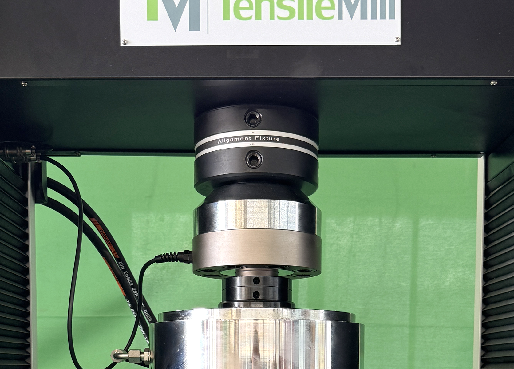
Which Alignment Tools and Procedures Prepare TM-EML Series UTMs for NADCAP or Similar Accreditation?
TM-EML testing frames support formal alignment workflows used for NADCAP and comparable audit programs. Operators can verify axiality with alignment fixtures compatible with ASTM E1012 and with ISO-aligned practices. These tools measure load-string symmetry, bending strain, and force distribution so you can adjust grips, adapters, and crosshead centering before a calibration visit. GenTest software guides stepped loading and captures alignment data, then generates a traceable report for auditors.
In practice, select an alignment bar or multi-gage fixture that matches your grip type, install it between the upper and lower adapters, and zero the sensors. Run a controlled tension profile in GenTest, add compression if required by your audit scope, and watch live axiality and bending indicators. If readings show eccentricity, correct grip parallelism, change or reface worn jaw faces, confirm adapter concentricity, and recenter the crosshead, then repeat the sequence until bending falls within your program limits. Save the GenTest protocol with operator ID, instrument serial numbers, and calibration references to document the alignment state. Our team can help match the correct alignment fixture to your frame and jaw style for a smooth audit.
If you would like to review compatibility and reporting features, you can read more on the
TM-EML Series C UTM product page.
What Comes Standard With a TM-EML Series Universal Testing Machine, and Which Options Are Most Popular?
Each TM-EML order ships ready to test with the load frame, a closed-loop AC servo controller, a precision load cell matched to the selected capacity, and the GenTest software package. Basic tensile grips or compression platens are supplied according to the methods specified on the order, and the machine includes safety features such as an emergency-stop circuit, travel limit switches, and motor protection.
If you would like to compare capacities and accessory choices, you can review technical details on the
TM-EML Series C UTM page.
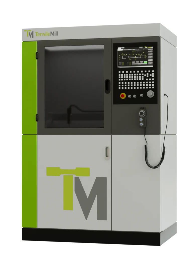
What Is the TM-EML Series C Universal Testing Machine and Which Applications Is It Designed For?
The TM-EML Series C is a dual-column electromechanical universal testing machine built for mid to high force tensile, compression, flexural, and cyclic programs. A servo-driven direct drive with a rigid, FEM-refined frame provides stable closed-loop load and crosshead control, along with precise column alignment during extended or multi-stage sequences.
Typical use spans modulus, yield and ultimate tensile strength, elongation, flexural properties, and deformation behavior across metals, reinforced plastics, composites, elastomers, and foams in production QC, engineering labs, and research. The platform supports methods such as ASTM E8 for metallic tension, ASTM D638 or ISO 527 for plastics, and ASTM D790 for flexure. When high-accuracy strain data is needed, the system works with appropriate grips, fixtures, and extensometry to capture uniform, repeatable measurements during monotonic or basic cyclic routines.
If you would like to review capacities, controller options, and typical test configurations, you can explore details on the
TM-EML Series C Universal Testing Machine product page.
Which Materials and Specimen Types Suit the TM-EML Series C Mid- to High-Force Range?
This mid to high force electro-mechanical UTM is built for programs that need greater frame rigidity and capacity than low-force benchtop systems. Suitable materials include carbon and stainless steels, heat resistant alloys, structural plastics and engineering polymers, fiber reinforced composites, elastomers and rubbers, rigid and flexible foams, thin films, and biodegradable substrates.
Use this platform for flat dog-bone coupons, round machined bars, and custom research geometries used in aerospace, automotive, and academic labs. It supports tensile, compression, flexural, peel, shear, and cyclic profiles while delivering consistent accuracy from 1,125 lbf to 11,240 lbf (5 kN to 50 kN). Match the application with appropriate tooling, such as wedge or self-tightening grips for metals, pneumatic grips for polymers and films, compression platens for crush testing, and three or four point bend fixtures for flexure. For standards-based work, common methods include ASTM E8 for metallic tension, ISO 527 or ASTM D638 for plastics, ASTM D790 for flexural testing, ASTM D412 for elastomers, and ASTM D882 for thin films. This range and fixture flexibility let one system handle both day-to-day QA and research tasks with dependable results.
If you would like to compare capacities, fixtures, and software options, you can review technical details on the
TM-EML Series C UTM product page.
What Force Capacities Does the TM-EML Series C UTM Offer, and How Do I Select the Right Load Rating?
TM-EML Series C load options are 1,124 lbf (5 kN), 2,248 lbf (10 kN), 4,496 lbf (20 kN), 5,618 lbf (25 kN), 6,744 lbf (30 kN), and 11,240 lbf (50 kN). Each configuration delivers Class 0.5 force accuracy across its working range and supports static and cyclic testing modes.
For sizing, target a capacity where your specimen’s peak force typically falls between about 10 to 70 percent of the load cell range. This operating window gives stable control, low noise, and consistent repeatability. As a quick check, estimate your failure load from prior runs or from comparable materials, then select the next load rating that keeps most results in the middle of the range. Example: if coupons usually break near 3,000 lbf (13.3 kN), a 4,496 lbf (20 kN) load cell places typical peaks around 67 percent, which is appropriate.
Choose higher-capacity frames when testing metallic coupons to ASTM E8, thick composite laminates or reinforced plastics to ISO 527, or when using long-travel grips, high-temperature fixtures, or dual-space setups that demand added stiffness. If your program includes occasional outliers with much higher forces, size for those events so you avoid frequent load cell changes while keeping everyday tests within the preferred range.
If you would like to review specifications or compare frame options, you can explore details on the
TM-EML Series C Universal Testing System product page.
What Are the TM-EML C-Class Dimensions, Working Height, and Weight for Benchtop and Floor-Standing Configurations?
Both layouts share the same footprint, approximately 30.3 in × 25.2 in (770 mm × 640 mm). A typical benchtop single-space configuration stands about 66.9 in high (1700 mm), provides 39.4 in of vertical crosshead travel (1000 mm), and weighs about 816 lbs (370 kg). Extended or dual-space systems used as floor-standing units, or on a dedicated stand, are about 90.6 to 92.9 in high (2300 to 2360 mm), offer up to 63.0 in of travel (1600 mm), and weigh about 926 lbs (420 kg).
Working height is dictated by crosshead travel, so selection comes down to your specimens and fixtures. For routine metals or plastics testing with moderate gauge lengths and standard grips, the single-space frame keeps the lab footprint compact while delivering full-stroke flexibility. If you run long specimens, tall environmental fixtures, or large compression setups, the extended frame preserves clearance above and below the test space without compromising stroke. The common base size simplifies bench or pedestal placement, and the heavier dual-space build adds rigidity for mid to high force applications.
If you would like to review full dimensions, travel options, and accessories, you can read the details on the
TM-EML Series C Universal Testing Machine page.
How Does the TM-EML C-Series Dual-Column Frame Improve Stiffness and Alignment vs Single-Column, Lower-Capacity Models?
The C-Series dual-column frame delivers higher structural stiffness and more stable load-string alignment than single-column and lower-capacity TM-EML machines, especially at elevated forces and with long-travel fixtures.
Twin columns with synchronized, preloaded ball screws and dual guide rails distribute bending moments across both uprights, which reduces lateral deflection and crosshead rotation. A reinforced crosshead and wider column spacing help keep platen or grip faces parallel across a larger work zone, supporting heavier grips, long extensometers, or environmental accessories without introducing meaningful side load. With rated capacities up to 11,240 lbf (50 kN), the C-Series maintains alignment during cyclic profiles and when testing metals or advanced composites where modulus, yield, and tensile strength accuracy depend on low frame compliance.
Single-column and smaller-capacity frames are compact and efficient for lower forces, typically up to 2,248 lbf (10 kN), yet their single load path and narrower stance make them more sensitive to off-center loading and heavy fixturing, which can affect strain uniformity and break location. Labs that verify alignment to ASTM E1012, or run high-precision tensile methods such as ASTM E8 or ISO 6892-1, often select the C-Series geometry to achieve repeatable results across a wider range of specimens and accessories.
If you would like to compare frame architecture and capacities, you can review technical details on the
TM-EML Series C UTM product page.
What Are the Maximum Crosshead Travel, Usable Test Width, and Effective Test Space on the TM-EML Series C UTM?
Usable test space on the Series C is defined by the vertical crosshead travel and the clear distance between the columns. The clear test width is 16.5 in (420 mm) across all configurations. Crosshead travel depends on frame height: standard single-space provides 39.4 in (1000 mm), and standard dual-space provides 35.4 in (900 mm) in the primary test space. Extended frames add headroom, with 51.2 in (1300 mm) for the 300 mm single-space and 63.0 in (1600 mm) for the 600 mm single-space. Dual-space extended options provide 47.2 in (1200 mm) and 59.1 in (1500 mm) in the main space.
In practice, effective test height equals the listed travel minus the installed hardware. Subtract the combined grip stack, fixtures, extensometers, or any environmental chamber from the values above. For example, a standard single-space frame with 39.4 in (1000 mm) of travel, a 12.0 in (305 mm) total grip length, and a 2.0 in (51 mm) clip-on extensometer leaves about 25.4 in (645 mm) of working height. Extended frames are preferred for long coupons, assemblies with deep jaw faces, or high-elongation materials that need extra displacement.
If you would like to review frame options and dimensional drawings, you can read more on the
TM-EML Series C Universal Testing Machine page.
What Crosshead Speed Range and Strain-Rate Control Does the TM-EML Series C Support?
The TM-EML Series C supports a broad crosshead speed envelope for both precision low-rate studies and high-throughput testing. Standard test speeds reach about 35.43 in/min (900 mm/min), with a high-speed return of approximately 59.06 in/min (1500 mm/min). Ultra-slow motion is available down to roughly 0.000002 in/min (0.00005 mm/min), suitable for controlled creep, relaxation, and very low strain-rate work.
A 1,200 Hz closed-loop digital servo regulates force, displacement, and strain, delivering stable strain-rate control across the full range. With an extensometer, you can program constant strain-rate ramps or holds for metals, composites, polymers, and long-elongation specimens without drift or speed or position mismatch. Crosshead rate translates to nominal strain rate based on gage length; for example, at 0.20 in/min (5.08 mm/min) on a 2.00 in (50.80 mm) gage length, the nominal crosshead-based strain rate is 0.10 min^-1. The available speed range supports common methods such as ASTM E8 for metals and ISO 527 for plastics when configured with the proper grips and feedback mode.
If you would like to review configuration options and speed capabilities, you can explore details on the
TM-EML Series C Universal Testing System product page.
Which Load Cells Work With the TM-EML C-Series UTM, and Can Multiple Load Cells Be Interchanged on One Frame?
The C-Series accepts plug-in load cells covering 112 to 11,240 lbf (0.5 to 50 kN). Each transducer is factory calibrated to Class 0.5 and includes TEDS auto recognition, so the controller identifies the sensor, loads the correct calibration file, and sets the range as soon as it is mounted. This removes manual span entry and reduces setup time and operator error.
Yes, multiple load cells can be used on the same frame. Labs often pair a low-capacity sensor for delicate plastics or foils with a higher-capacity unit for metals, moving between methods such as ASTM D638 and ASTM E8 without changing hardware. The bidirectional design supports both tension and compression, while overload logic and side-force protection help protect the element during changeovers or off-axis breaks. After a swap, the software reads the TEDS profile, zeros the force channel, and confirms capacity, which streamlines workflows when switching between small specimens and structural samples and helps maintain stable measurements over repeated changeouts.
If you would like deeper specifications and compatible accessories, you can review details on the
TM-EML Series C Universal Testing System page.
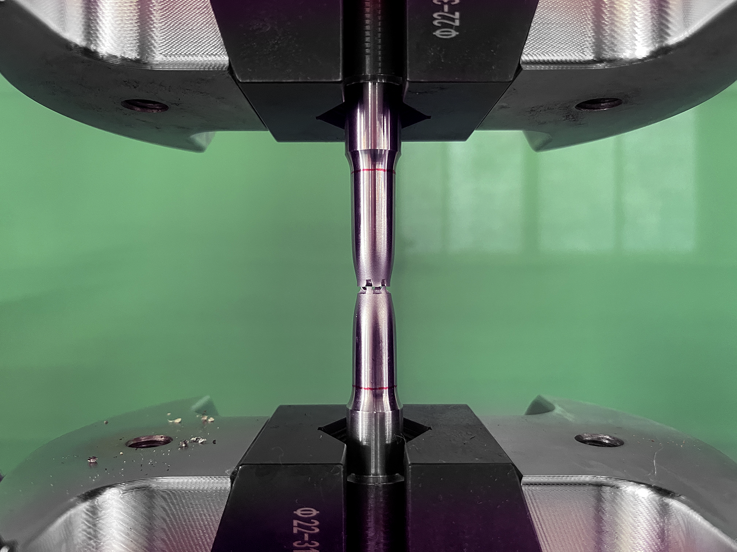
How Does the TM-EML Series C Protect Delicate, Brittle, or High-Strength Specimens During Gripping, Preload, and Early Test Stages?
The controller applies a low, precisely managed preload using real-time force feedback, so initial contact and gripping occur without sudden spikes that could mark thin films, fracture brittle composites, or notch high-strength coupons. Adaptive PID logic continuously tunes actuator output to avoid overshoot while ramping to the first setpoint.
During alignment and jogging, closed-loop position and force windows keep the crosshead inside safe boundaries to prevent unintended loading. Collision detection monitors the rate of force change and stops motion if an abnormal rise is detected. Hardware and software limits work together, including dual limit switches and an overload cutoff at 103% of rated capacity, to halt movement immediately under unsafe conditions. When the machine is paired with pneumatic grips, a digital pressure-control module delivers repeatable clamping force in lbf and N, reducing slippage at test initiation without crushing the specimen.
Across capacities from 1,124 lbf to 11,240 lbf (5 kN to 50 kN), these layered protections provide a gentle start and stable early-stage control, helping operators move from specimen placement to the first data points with confidence and consistent results.
If you would like to review protection features, software control, and accessories, you may explore the details on the
TM-EML Series C UTM product page.
What Extensometers Are Recommended for the TM-EML Series C UTM, Including Long-Travel, Non-Contact, and High-Temperature Options?
The Series C electromechanical UTM is compatible with clip-on, non-contact video, long-travel, and high-temperature extensometers, allowing accurate strain measurement from modulus through elongation at break. For most metals, plastics, and composites, precision clip-on units deliver stable, low-noise readings over a defined gauge length suitable for modulus and yield calculations.
For elastomers, foams, and very ductile polymers, non-contact video extensometers or long-travel contact arms track large displacements without removing the sensor mid-test, which helps prevent data gaps. Elevated temperature work inside environmental chambers is supported with high-temperature extensometers that use ceramic rods and heat-rated cabling for reliable signal quality during heated tensile, creep, or stress relaxation procedures. Selection should align with your method and material behavior, for example gauge-length control for ASTM E8 metals or ISO 527 plastics, required travel, surface condition, and whether contact on the specimen is acceptable. The system integrates the extensometer channel so operators can capture modulus, yield, and post-yield strain in a single test sequence.
If you would like to review system details and typical accessory compatibility, you can read more on the
TM-EML Series C UTM product page.
Is a Safety Enclosure Available for the TM-EML C-Series Dual-Column UTM, and When Is It Recommended?
Yes. A purpose-built safety enclosure is available for the dual-column TM-EML C-Series universal testing machine. It features a rigid aluminum frame with impact-resistant polycarbonate panels and a door-interlock system that halts crosshead motion when the door is open, supporting debris containment and operator guarding.
The enclosure is typically selected for high-force metal testing, brittle composites or plastics that can fragment at break, extended cyclic or fatigue programs that run unattended for long durations, and any workflow that benefits from controlled access around moving grips, fixtures, and load strings. Production QA cells, shared academic labs, and facilities operating under formal EHS policies often standardize on the enclosure to promote consistent guarding, reduce airborne fragments, and modestly dampen test noise. For teams that change specimens frequently, the interlock and clear sightlines help technicians stage specimens and verify alignment without entering the machine envelope, which streamlines throughput while maintaining safe operating practices.
If you would like to review guarding options and specifications, you can learn more on the
TM-EML Series C UTM product page.
Can the TM-EML C-Class UTM Be Supplied With an Integrated Industrial Touchscreen PC, and Is a Separate Workstation Required?
Yes. The TM-EML C-Class UTM can be supplied with an integrated industrial touchscreen PC mounted to the load frame, allowing fully stand-alone operation. A separate workstation is not required.
With the touchscreen terminal, operators run GenTest software directly at the machine, select or edit test methods, view live graphs, and produce reports at the point of testing. For labs that prefer a desktop workflow, the system can also be operated from an external PC, so either interface may be used interchangeably based on space constraints, operator preference, or IT policies. Many teams use the integrated terminal for routine testing while keeping a workstation available for method development, data review, or centralized data management.
If you would like to review integrated control options and software features, you can learn more on the
TM-EML Series C UTM product page.
How Fast Is Changeover for Grips, Fixtures, Load Cells, and Dual-Space Setups on the TM-EML Series C UTM?
Routine reconfiguration on the TM-EML Series C typically takes only a few minutes with a trained operator. Grips and fixtures mount to standardized adapters, so the workflow is to loosen the mechanical fasteners, remove the current accessory, install the new one, and verify coaxial alignment in GenTest before zeroing load and extension. Load cells attach through a quick mechanical interface with a keyed connector, and the system reads the sensor identity and stored calibration automatically, avoiding manual scaling.
On dual-space frames, switching between upper and lower test spaces is straightforward. The operator moves the crosshead to the required space, confirms travel limits, selects the appropriate method and active test space in GenTest, and performs a quick alignment check. Labs that reconfigure frequently often keep commonly used platens, wedges, or pneumatic grips staged in each space, which shortens setup time for alternating tensile and compression work.
For the fastest changeovers, keep jaw faces, adapters, and alignment rods organized at the machine, and use consistent fixture heights so the crosshead repositioning is minimal. A saved library of method templates in GenTest also reduces keystrokes between material families and test modes.
If you would like a deeper look at frame configurations, accessories, and software workflows, you can review technical details on the
TM-EML Series C Universal Testing Machine product page.
How Does the TM-EML Series C Manage ASTM, ISO, EN, and GB/T Test Methods and Templates in GenTest?
GenTest on the TM-EML Series C UTM includes a built-in library of standardized methods covering tensile, compression, flexural, and cyclic testing across ASTM, ISO, EN, and GB/T families. Each template carries the control mode selection, speed or strain rate, preload routine, break detection, result items, and reporting layout. An operator loads the required standard, enters specimen dimensions, and starts the test without rebuilding the method.
For advanced workflows, any standard can be copied and saved as a lab template with custom naming, acceptance limits, extra calculations, or compliance notes. Methods can be organized by material, department, or standard family, so production, QA, and R&D see only what they use. Examples include grouping ASTM E8 for metals or ISO 527 for plastics. Role-based permissions allow supervisors to create and lock templates while day-to-day users select from a controlled list, which streamlines setup, reduces operator variation, and supports consistent results across shifts.
If you would like to review how method libraries and permissions are implemented, you may explore details on the
TM-EML Series C UTM product page.
What Are the Position, Speed Accuracy, and Force Resolution Specifications for the TM-EML Series C UTM?
Position control provides micro-displacement feedback with a resolution of 0.0000004 in (0.01 µm). Crosshead speed accuracy is ±0.2% of the set speed across the full operating range, from ultra low creep or relaxation rates to high travel speeds used for throughput. Force measurement uses high-resolution load cells with a resolution of 1 part in 600,000 of full scale.
Accuracy is verified to GB/T 16825.1, ISO 7500, and ASTM E4. The system meets Class 0.5 from 0.2 to 100% of rated load in the 112.4 to 11,240 lbf range (500 N to 50 kN), and from 0.4 to 100% in the 2.25 to 56.2 lbf range (10 N to 250 N). A 1,200 Hz control loop and data acquisition rate support stable force, displacement, and strain control during static tests and low frequency cyclic routines, which helps with tasks like creep, relaxation, modulus tracking, and yield characterization on both delicate polymers and high-stiffness metals.
If you would like to review expanded specifications and configuration options, you may explore the
TM-EML Series C UTM page for more details.
How Does the Pneumatic Grip Control Module Work on the TM-EML Series C UTM and What Are the Workflow Benefits?
The optional pneumatic grip control module provides closed-loop, digital pressure regulation for the upper and lower grips on the TM-EML Series C. Operators set and monitor clamping pressure from the handheld console or directly in GenTest software, with independent channels for each grip. An integrated electronic regulator maintains the target pressure during the test, and quick-connect air ports make it straightforward to attach pneumatic side-action grips or other air-operated fixtures for tensile or compression work.
For routine testing, this module improves repeatability by applying the same clamping force every time, which reduces operator-to-operator variation and helps protect delicate or compliant specimens from over-tightening. Preset profiles let labs switch materials or jaw faces without re-tuning pressure, which shortens changeovers and speeds batch throughput. Built-in safety logic ties grip actuation to machine state, so clamping remains disabled until the test space is clear and the frame is ready, helping prevent unintended jaw movement during setup.
If you would like to review control options, pressure presets, and compatible pneumatic grips, you can learn more on the
TM-EML Series C Universal Testing System page.
What Reporting, Graphing, and Data Export Features Does GenTest Provide for TM-EML Series C Users?
GenTest for the TM-EML Series C delivers real-time visualization and flexible reporting for routine QA documentation and research analysis.
Live charts display force-displacement, stress-strain, and time-based traces simultaneously. Operators can zoom, pan, overlay multiple specimens, compare batches, and mark yield or break regions, while key results such as peak load, offset yield, elongation, modulus, and energy appear directly on the graph. When applicable, report templates may include method identifiers such as ASTM E8 or ISO 527 to align with your material program.
Reporting and export options include PDF summaries with configurable headers, logos, and sign-off blocks, Excel and CSV datasets for raw and calculated channels, and high-resolution image output in PNG or SVG for documentation. Laboratories that synchronize results can generate structured data packages for LIMS or ERP, with time stamps, specimen IDs, operator fields, and pass or fail flags. Users may choose full-rate or down-sampled data to balance file size and post-processing needs.
If you would like to explore software capabilities alongside the hardware, you can review technical details on the
TM-EML Series C Universal Testing System product page.
Can the TM-EML Series C Dual-Column UTM Perform Ultra-Low Strain-Rate, Creep, Relaxation, or Micro-Displacement Tests?
Yes. The C-Class dual-column UTM supports ultra-low strain-rate work, time-dependent creep and stress-relaxation sequences, and micro-displacement control. The servo drive delivers stable crosshead motion from 0.00000197 in/min (0.00005 mm/min), and the closed-loop controller samples force, position, and strain at 1200 Hz for consistent control during long dwells and load holds.
For creep or relaxation, operators can program constant-load, constant-stress, or constant-strain holds with multi-stage ramps, dwell times, and recovery steps. High-resolution position feedback with adaptive PID control maintains smooth motion at very low speeds, which is valuable for polymers, elastomers, solders, thin films, and other materials that deform slowly or respond to small displacement changes. GenTest software provides ready-to-run modules for common procedures and allows custom templates with event-based triggers, autosaves, and time-based data logging for extended tests. The platform’s stable low-speed behavior reduces drift during multi-hour sequences and supports repeatable results when using clip-on or optical extensometers.
If you are planning time-dependent tests, you can review capabilities and software options on the
TM-EML Series C Universal Testing System product page.
Can the TM-EML Series C UTM Integrate With External Sensors, Environmental Chambers, and Custom R&D Accessories?
Yes. The Series C controller is designed for multi-device workflows, with synchronized data acquisition that keeps auxiliary signals aligned with force and crosshead position.
The system provides six high-resolution input channels sampled at 1200 Hz, allowing direct connection of extensometers, strain gauges, displacement sensors, temperature probes, and other analog instruments. Force, displacement, and every auxiliary channel are captured on the same time base, so modulus, yield, and creep calculations reflect true, time-correlated behavior.
Environmental chambers, heating and cooling units, and high-temperature extensometers interface through GenTest. The accessory manager identifies compatible devices, applies channel types and units, and maintains channel-to-method bindings across operators and test methods. For custom R&D setups, users can map bespoke sensors to available channels, create derived variables, and script events such as chamber ramps or pneumatic grip actuation within the test method. This approach supports temperature-dependent work, including elevated-temperature tensile studies often performed to ASTM E21, while keeping setup time low and throughput predictable for QA and research labs.
If you would like a closer look at I/O capabilities and accessory options, you can review technical details on the
TM-EML Series C UTM product page.
Does the TM-EML Series C UTM Support Cyclic, Multi-Stage, and Waveform-Controlled Load Profiles?
Yes. The Series C electromechanical test frame runs cyclic, staged, and waveform driven programs using advanced sequencing in GenTest. It supports tension and compression cycling, incremental steps, load hold segments, and custom ramps with high rate closed loop feedback and adaptive control for precise force, strain, or displacement control.
Operators can build multi-stage profiles with variable speed, force, strain, or displacement targets to study fatigue behavior, stress relaxation, and time dependent deformation. Available waveforms include sine, triangle, trapezoid, and user defined shapes, with stable amplitudes and frequencies suited to mid to high force materials. Profiles may include preconditioning, dwell, and recovery segments, and each sequence can be saved as a reusable template for research, production, or accreditation workflows.
If you would like to explore control options and software capabilities, you can review technical details on the
TM-EML Series C Universal Testing Machine page.
How Do I Select Load Capacity and Test Speed for an Electro-Mechanical Universal Testing Machine?
Start with the highest expected specimen load. Estimate peak force by multiplying ultimate tensile strength by the smallest cross section, then choose a frame rated 2 to 3 times higher. Common ranges are 10 kip, 30 kip, and 60 kip (45 kN, 135 kN, and 267 kN). For thin plastics, elastomers, or biomedical parts, 225 lbf to 1,000 lbf (1 kN to 4.4 kN) often suffices.
Match control mode and speed to materials and methods. For metals to ASTM E8 or ISO 6892-1, prioritize strain or strain-rate control with an extensometer, not crosshead speed alone. A practical speed envelope is 0.002 to 20 in/min (0.05 to 500 mm/min); labs running plastics to ASTM D638 or ISO 527 often need up to 40 in/min (1,000 mm/min). Verify rate accuracy of ±0.5 percent and position resolution near 0.00004 in (1 µm) for consistent results.
Use interchangeable load cells so routine tests fall between 10 percent and 90 percent of capacity. For example, pair a 10 kip (45 kN) cell for structural metals with a 500 lbf (2.2 kN) cell for thin polymers or adhesives. Select grips rated above the expected test load and an extensometer with the correct gauge length, such as 1.0 in or 2.0 in (25 mm or 50 mm), to meet specimen geometry and relevant standards.
If you would like specification guidance tailored to your lab, you can review options on the
UTM Electro Mechanical equipment page and connect with our team for configuration details.
How Do I Select Load Capacity, Travel, and Speed for an Electromechanical UTM?
Start by estimating the highest force your specimens will require, then size the frame at 1.2 to 1.5 times that peak. For example, if trials show 8,000 lbf (35.6 kN), a 10,000 to 15,000 lbf (44.5 to 66.7 kN) machine provides headroom for tough batches, larger cross sections, or future programs. Verify the load cell meets Class 1 or better accuracy per ASTM E4 or ISO 7500-1, and confirm resolution is adequate for low-force segments like yield-by-offset.
Match speed and control to your methods. A practical range is roughly 0.002 to 20 in/min (0.05 to 500 mm/min), with stable closed-loop control at very low speeds for modulus, creep, or stress-relaxation work. If you run strain-rate or crosshead-rate procedures in ASTM E8, ISO 6892-1, or ISO 527, ensure the controller supports constant strain rate and easy transitions between method steps. Choose travel that accommodates grips, extensometers, and anticipated elongation; 20 in (510 mm) covers most metals and plastics, while high-elongation materials may need 30 to 40 in (760 to 1,020 mm).
Evaluate the ecosystem. Confirm data acquisition at 1,000 Hz or higher for clean stress-strain curves, compatibility with clip-on or non-contact extensometry, and the availability of tension, compression, and flexure fixtures. Consider safety, power, and lab footprint, for example 120 V single-phase or 230 V single-phase, and plan for calibration and verification intervals aligned to your quality system.
If you would like to review configuration options for electromechanical universal testing frames, you can connect with our team on the
Contact Us page.
How Do I Choose the Right Electromechanical UTM Capacity and Speed?
Start with capacity. Estimate the highest failure load for your specimens, then select a frame rated at 1.2 to 2.0 times that value to preserve measurement linearity and accommodate grips or chambers. Size the primary load cell so typical peaks fall between 50 and 90 percent of capacity. If you also test thin plastics or small wires, add a secondary load cell, for example 50 lbf to 500 lbf (220 N to 2.2 kN). As a reference, if most metal samples break near 8,000 lbf (35.6 kN), a 10,000 to 20,000 lbf (44.5 to 89 kN) frame with a 10,000 lbf (44.5 kN) load cell is a practical choice.
Confirm speed and travel next. A crosshead speed range covering 0.002 to 20 in/min (0.05 to 500 mm/min) addresses common plastics methods in ASTM D638 and ISO 527, and metals preloads or modulus ramps. Plan for at least 30 in (760 mm) vertical travel when using long extensometers, temperature chambers, or long-specimen grips. Look for closed-loop control in force, displacement, and strain, along with high-resolution position feedback and adequate data rates for your material behavior.
Validate compliance and accessories. For metals, verify force calibration to ISO 7500-1 Class 1 or Class 0.5 and ASTM E4, and consider an alignment device per ASTM E1012 for ASTM E8 or ISO 6892-1 testing. Match grips to the application, such as wedge or hydraulic grips for metals and pneumatic grips for thin plastics, and select a clip-on or automatic extensometer meeting ASTM E83 Class B-1 or better.
If you would like personalized guidance on sizing and configuration, you can connect with our team on the
Contact Us page.
How Do I Select Load Capacity, Speed, and Extensometry for an Electromechanical UTM?
Start with the highest expected failure load and specimen dimensions. Choose a frame capacity that covers your peak load with 20 to 30 percent headroom. Use interchangeable load cells so routine tests run between 10 and 90 percent of the cell’s capacity. For example, if aluminum coupons fail near 12 kip (53 kN), a 22 kip (100 kN) machine with a 22 kip cell plus a secondary 2 kip (10 kN) cell delivers both headroom and fine resolution. Typical electromechanical systems span about 225 lbf to 220 kip (1 kN to 1000 kN).
Match speed capability to your methods. For metals guided by ASTM E8, prioritize low-speed stability and closed-loop strain control for yield and modulus work. For plastics under ASTM D638 or ISO 527, ensure the controller holds constant rates across roughly 0.2 to 20 in/min (5 to 500 mm/min), with speed accuracy near ±0.5 percent of setpoint and smooth transitions between preload, approach, and test segments.
Select extensometry by gauge length, travel, and class. Metals often use clip-on units at 2 in (50 mm) that meet ASTM E83 Class B1 or better; plastics frequently require 1 in to 2 in (25 mm to 50 mm) gauge lengths and ISO 9513 Class 1. Plan for total travel of about 1 in (25 mm) for metals and up to 4 in (100 mm) or noncontact video for high-elongation materials. Confirm lab conditions and utilities, such as 59 to 86 °F (15 to 30 °C) and 120 V or 230 V power, align with your testing plan.
If you would like to discuss sizing and configuration, you can connect with our team on the
Contact Us page.
How Do I Choose Load Cell Capacity For An Electromechanical UTM?
Start by estimating the highest force your specimens will generate. Multiply the expected ultimate tensile strength in psi by the smallest cross-section in in² to obtain force in lbf, then convert to kN as needed. Account for worst-case conditions such as elevated strength after heat treatment or thicker sections, and include typical fixture weight if it contributes to force measurement.
Select a capacity that keeps routine tests within about 20% to 80% of the load cell rating. Many systems achieve Class 1 or Class 0.5 accuracy per ASTM E4 or ISO 7500-1, typically ±1% or ±0.5% of reading from roughly 0.2% to 100% of capacity. If your workload spans small plastics to high-strength metals, use multiple interchangeable cells, for example 1,000 lbf (4.45 kN) for thin coupons and 10,000 lbf (44.5 kN) or 50,000 lbf (222 kN) for stronger parts, with auto-recognition to prevent setup errors.
As a quick example, a strip with 0.25 in² area and 60,000 psi UTS requires about 15,000 lbf (66.7 kN). A 20,000 lbf (89 kN) cell places testing in the optimal range. Confirm the frame’s maximum capacity exceeds the largest cell, apply a 30% to 50% safety margin, and verify force at least annually or after relocation or suspected overload using ASTM E4 or ISO 7500-1 procedures. Avoid near-capacity sustained loading, off-axis forces, and impact; use proper grips and alignment to protect the cell and maintain measurement fidelity.
If you would like to discuss load cell sizing for your application, you can connect with our team on the
Contact Us page for guidance.
Which Load Cell, Speed Range, and Extensometer Should I Choose for a 1,100 to 11,200 lbf (5 to 50 kN) Electromechanical UTM?
Start with the highest expected force for your program. Select a load cell so routine peaks fall between 10 to 90 percent of its capacity. If your metals work typically reaches about 6,000 lbf (26.7 kN), a 10,000 lbf (44.5 kN) sensor preserves accuracy and headroom. For mixed materials, keep an additional 1,100 lbf (5 kN) or 2,200 lbf (10 kN) cell for low-force plastics and elastomers. Verify load measurement performance to ASTM E4 during installation and at scheduled intervals.
Match drive capability to method requirements. Metals often run at modest crosshead rates near 0.02 to 0.2 in/min (0.5 to 5 mm/min) to support yield characterization in ASTM E8. Many plastics methods operate around 2 to 20 in/min (50 to 500 mm/min) per ISO 527 or ASTM D638. Ensure the controller offers stable displacement or strain control for transitions around yield and modulus segments, and confirm that rate accuracy remains within your lab’s tolerance.
Choose extensometry by strain range. For most metals, use a clip-on with 1.0 in (25 mm) gauge length and at least 0.4 in (10 mm) travel. Plastics and composites commonly benefit from 2.0 in (50 mm) gauge length and 2 to 4 in (50 to 100 mm) travel to capture necking or high elongation. For elastomers or thin films, a non-contact video extensometer with up to 8 in (200 mm) measurement range provides reliable strain without slippage or knife-edge marking.
If you are evaluating mid-capacity tensile systems, you can review specifications and options on the
TM-EML Series C UTM equipment page.
How Do I Select Load Cell Capacity And Extensometry For A 1,100 To 11,200 lbf (5 To 50 kN) Electromechanical UTM?
Choose a load cell so your specimen’s expected peak falls between roughly 10% and 90% of the sensor’s capacity. For example, if your highest peak is 3,000 lbf (13.3 kN), a 5,000 lbf (22 kN) cell offers good headroom and resolution. When testing delicate materials below 50 lbf (222 N), use a lower-capacity sensor to maximize signal-to-noise. Swappable tension-compression cells let one frame cover 1,100 to 11,200 lbf (5 to 50 kN) efficiently.
Match extensometry to material behavior and the governing method. For metals to ASTM E8, a clip-on axial extensometer with 2 in (50 mm) gauge length and suitable travel is typical. For plastics to ASTM D638 or ISO 527, select long-travel clip-on or non-contact video systems when strain may exceed 100% elongation, and use appropriate knife edges or adhesive markers to avoid slippage.
Set crosshead speed from the target strain rate and gauge length. Crosshead speed equals strain rate multiplied by gauge length. If you need 0.005 in/in/min for metals with a 2 in (50 mm) gauge, set about 0.01 in/min (0.25 mm/min). Verify grip style and face selection as well, for example serrated wedge grips for metals or rubber-faced pneumatic grips for films, to prevent jaw breaks and maintain alignment.
If you are evaluating mid-capacity testing frames, you can review technical details on the
TM-EML Series C UTM product page.
How Do I Choose Load Cells and Grips for a 1,100 to 11,200 lbf (5 to 50 kN) UTM?
Select a primary load cell so your expected peak forces fall between about 10 to 90 percent of its capacity. On a 1,100 to 11,200 lbf (5 to 50 kN) frame, many labs keep multiple cells available, for example 1,100 lbf (5 kN) for elastomers and thin plastics, 2,200 lbf (10 kN) for most ASTM D638 or ISO 527 plastics, and 11,200 lbf (50 kN) for metals that approach ASTM E8 ultimate loads. Interchangeable, bidirectional cells with TEDS style auto recognition help preserve calibration and simplify changeovers.
Match grips to specimen behavior and surface. Self-tightening wedge grips with serrated faces limit slip on metals for ASTM E8 round or flat sections. Pneumatic grips with rubberized or fine serrations manage clamping on polymers and composites per ASTM D638 and ISO 527, and are gentler on thin coupons. For flexure, use 3 point or 4 point fixtures sized to your span and thickness. Choose faces that cover the reduced section, typically 1 in to 2 in (25 mm to 50 mm) wide, and ensure the grip interface matches the machine adapters.
Set crosshead rates and strain measurement to the governing method. The electromechanical drive supports precise low rates for creep and speeds up to about 94.5 in/min (2400 mm/min) for throughput. For modulus, yield, and elongation control, pair the load cell with a clip on or non contact extensometer. Maintain annual force verification to ASTM E4 or ISO 7500-1 Class 0.5, and check alignment to minimize bending effects.
If you would like to review capacities, software options, and accessory compatibility, you can explore the details on the
TM-EML Series C UTM product page.
How Do I Choose Load Cells, Grips, and Extensometers for a 1,124 to 11,240 lbf (5 to 50 kN) Universal Testing Machine?
Select load cells so expected peak forces fall between about 10% and 90% of the sensor’s capacity for best resolution and accuracy. For mixed test programs, pair a higher-capacity cell at 11,240 lbf (50 kN) with a secondary 1,124 or 2,248 lbf (5 or 10 kN) cell for low-force work. Verify performance to ASTM E4 or ISO 7500-1 at installation and at defined intervals, and keep the cell within its overload limit during break events.
Grip choice follows specimen geometry and standard. For metals to ASTM E8 or ISO 6892-1, use mechanical wedge grips rated above the expected maximum force, typically by 20% or more, with appropriate flat or V-jaw faces for 0.25 to 1.0 in (6 to 25 mm) diameter rounds or 1.0 in (25 mm) wide flats. For plastics to ASTM D638 or ISO 527, pneumatic grips with serrated or rubber faces improve repeatability on 0.5 to 1.0 in (13 to 25 mm) wide blanks. Thin films benefit from capstan or roller grips, 2 to 4 in (50 to 100 mm) diameter, to prevent jaw slippage and edge tears.
Match extensometers to the strain range and standard. Typical metal tests use a 2.0 in (50 mm) gauge length with at least 0.6 in (15 mm) travel. Plastics often use 2.0 in (50 mm) or 1.97 in (50 mm) gauge length clip-on or video systems. For high-elongation elastomers to ASTM D412, select long-travel or non-contact options and control crosshead speed within your method, for example 0.02 to 20 in/min (0.5 to 500 mm/min), to achieve the specified strain rate.
If you would like application-specific guidance, you can review configuration options on the
TM-EML Series C UTM product page and see what best fits your lab’s methods.
How to Select Load Cells and Extensometers for a 1,124 lbf to 11,240 lbf (5 kN to 50 kN) Electromechanical UTM
Size the load cell so your expected peak force sits within the middle of its range for both resolution and accuracy, typically 20 to 80 percent of capacity. For example, a metal sample expected to reach 6,000 lbf (26.7 kN) pairs well with a 10,000 lbf (44.5 kN) cell, while thin plastics at 150 lbf (0.67 kN) benefit from a 500 lbf (2.22 kN) cell. Multi-cell setups with quick adapters let you switch capacity to match the specimen without sacrificing measurement fidelity.
Match the extensometer to material behavior and the governing method. For metals to ASTM E8 or ISO 6892-1, a clip-on unit with 1 in (25 mm) gauge length and about 0.50 in (12.5 mm) travel captures modulus and yield precisely. For plastics to ASTM D638 or ISO 527, use 2 in (50 mm) gauge length with long travel, around 4 in (100 mm), or a non-contact system for higher elongations.
Verify system performance to ASTM E4 at installation and at regular intervals. Before each test, zero force and strain after gripping, apply a small preload of 1 to 2 percent of expected maximum, and stabilize the lab near 68 °F (20 °C). These behaviors reduce slippage, improve repeatability, and keep measurement uncertainty within specification.
If you would like deeper specifications for your configuration, you can review details on the
TM-EML Series C UTM product page.
How Do I Choose Between Electromechanical and Hydraulic UTMs for Tensile Testing?
Start with the highest load you actually run. If routine work stays below about 50,000 lbf (220 kN), an electromechanical frame gives precise rate control and stable low-speed testing, down to roughly 0.002 in/min (0.05 mm/min). That behavior helps meet method-defined strain rates for plastics and elastomers under ASTM D638 or ISO 527, and for thin metals that need tight crosshead control.
Heavy sections of steel, rebar, or high-strength alloys often push past 110,000 lbf (500 kN). A hydraulic frame handles these forces with margin and can reach 2,000,000 lbf (9 MN) when required for ASTM E8/E8M or ISO 6892 work. Expect more maintenance and power demand, but the load headroom prevents mid-test pressure spikes from topping out the system.
Check the rest of the setup before deciding. If clamping forces exceed about 10,000 lbf (45 kN), plan on wedge or hydraulic grips and a frame stiff enough to limit bending. Keep alignment tight, below roughly 0.1 degree, to avoid off-axis loading. Confirm travel and accessory needs, such as chambers from -112 °F to 4000 °F (-80 °C to 2200 °C) and contact or optical extensometers. Many labs pair a 22,000 lbf (100 kN) electromechanical unit with a 110,000 lbf (500 kN) hydraulic unit to cover mixed programs.
You can review electromechanical and hydraulic frames, along with grips and accessories, on the
All Tensile Testing Equipment equipment page.
How Do I Decide Between Electromechanical And Hydraulic UTMs For My Lab?
Start with peak force and strain-rate control. If most work stays below about 22,000 lbf (100 kN), an electromechanical frame gives very stable low-speed control for methods like ASTM D638 or ISO 527. Operators can hold crosshead rates such as 0.02 to 20 in/min (0.5 to 500 mm/min) without hunting, which helps repeat modulus and yield points on plastics, films, and thin metals.
For heavy sections or high-strength alloys per ASTM E8 or ISO 6892, hydraulic machines handle sustained loads above 110,000 lbf (500 kN) and up to 2,000,000 lbf (9 MN). Wedge or hydraulic grips stop slippage on smooth specimens; serrated jaws bite, but switch to smooth or coated faces for soft metals. Align the specimen carefully with centering fixtures so the frame is not fighting bending.
Match accessories to the material. Clip-on extensometers work well for small strains on metals, while optical systems suit large elongations on elastomers. If testing outside ambient conditions, plan for chambers from −112 °F to 4,000 °F (−80 °C to 2,200 °C). Size the load cell so routine tests land near 60 to 80 percent of capacity, and confirm software supports your method library and report format requirements.
If you would like help matching force range, grips, and extensometers, you can review options on the
Tensile Testing Equipment equipment page.
How Do I Choose UTM Type And Capacity For Tensile Testing Of Forged Parts?
Select the frame by matching load range and control needs. Electro-mechanical machines excel at precise crosshead and strain-rate control for low to mid loads, ideal for sub-size coupons and routine alloy checks. Servo-hydraulic machines handle high-capacity work and thick sections, with comfortable headroom near 135 kip (600 kN) or 225 kip (1000 kN). If the expected peak load often exceeds about 60 kip (270 kN), hydraulic usually offers better durability and grip force for large forgings.
Size capacity from a quick calculation: capacity ≥ UTS × area, then add margin for off-axis effects and grip friction. Example: a 0.50 in (12.7 mm) round at 120 ksi (830 MPa) has 0.196 in² (126.5 mm²) area, predicted peak about 23.6 kip (105 kN). With a 30% margin, select at least 31 kip (138 kN). For shafts with localized hardening or variable section, consider a 50% margin.
Match accessories to the standard and geometry. For ASTM E8/E8M, use the specified gauge length, commonly 2.0 in (50 mm), and verify axial alignment per ASTM E1012. Choose wedge or hydraulic grips rated above machine capacity and sized to the grip section. If machining marks remain, apply longitudinal polishing to the gauge to reduce stress raisers before testing.
If you would like to compare frame types, capacities, and accessories, you can review details on the
Tensile Testing Equipment equipment page.
How Should Labs Plan Service and Calibration for Tensile Specimen Preparation and UTM Systems?
Plan annual force verification for UTMs to ASTM E4 or ISO 7500-1, with a maximum interval of 18 months. Reverify after relocation, repairs, or any out-of-tolerance result. In daily use, warm electronics 20 to 30 minutes, check zero, and confirm load-train seating and grip face condition. Log rate control and encoder checks. For alignment, follow ASTM E1012 when required by method or customer, or after grip or fixture changes.
For tensile sample preparation machines, set a practical PM rhythm. Monthly, check spindle runout and toolholders, aiming for ≤ 0.001 in (≤ 0.025 mm). Verify vise or chuck runout and, on lathes, tailstock center height. Cut a verification coupon and confirm critical dimensions to ± 0.001 in (± 0.025 mm) against a calibrated reference.
Budget for consumables and spares that wear, such as end mills, inserts, collets, jaw inserts, and belts. Schedule remote software updates on a set cadence, for example quarterly. Maintain one log that ties calibrations, PM tasks, certificates, and operator training to specific serial numbers. This documentation keeps audits predictable under ISO/IEC 17025, ASTM E4, and ISO 7500-1.
If you would like to review accredited methods and scheduling options, you can read the
Certification for Testing Equipment page to explore details on the information page.
How Should Tensile Tests Be Configured To Qualify Spacecraft Structural Materials?
Start with properly machined coupons that match the governing method for metals, typically ASTM E8 or ISO 6892-1. Use a straight or dog-bone geometry with a 2 in (50 mm) gage length and correct fillet radii, and target a smooth finish around 16 to 32 µin Ra (0.4 to 0.8 µm). For elevated temperature work, apply ASTM E21 procedures. Record the exact blank orientation, heat lot, and machining path so results track back to the flight drawing.
Select a frame and load cell that place expected failure loads in the middle of the range, for example a 50,000 lbf (222 kN) capacity machine for aluminum or titanium coupons. Verify axiality per ASTM E1012 using alignment fixtures, then choose wedge or hydraulic grips with jaw faces matched to thickness to avoid slip or jaw breaks. Control strain rate as required by the method and use an axial extensometer with a 1 or 2 in (25 or 50 mm) gage length for modulus, yield, and elongation.
If mission conditions drive testing beyond ambient, add a chamber that can run from about −320 °F to 1,200 °F (−196 °C to 650 °C). Use thermal shields, high-temperature or cryogenic grips, and specimen temperature verification at the gage section.
If you would like to review suitable frames and accessories for aerospace coupons, you can explore details on the
TM-EML Series D UTM product page.
How Should UTMs Be Configured for Testing Recycled Plastics and Metals?
Start with consistent specimen prep. Sort by resin or alloy lot, remove contamination, and machine coupons to the required standard. Common choices are ASTM D638 Type I for plastics and ASTM E8 subsize for metals, both with 2 in (50 mm) gauge marks. Condition plastics at 73 F and 50 percent RH. A light polish of the reduced section to about 32 µin Ra (0.8 µm) helps control strain localization on brittle blends.
Set the UTM to the method rate. For D638, crosshead speed often falls between 0.2 and 20 in/min (5 to 500 mm/min) depending on modulus. For E8, run the specified strain-rate segment using a clip-on or video extensometer set to 2 in (50 mm). Use wedge or pneumatic grips with faces matched to the material. Align with an alignment fixture, then apply a small preload, for example 10 lbf (45 N), only to remove slack.
Size the frame and load cell so peak load sits near 30 to 80 percent of capacity. If recycled aluminum peaks near 20,000 lbf (89 kN), a 50,000 lbf (222 kN) system provides headroom. The TM-EML Series D covers 11,240 to 224,800 lbf (50 to 1000 kN) with ±0.5 percent accuracy, fitting batches that range from polymers to structural metals.
If you would like to review frame capacities and software features, you can explore details on the
TM-EML Series D UTM product page.
How Do Labs Simulate Microgravity Tensile Tests On Earth?
For axial data relevant to microgravity, labs focus on removing gravity-related artifacts, not gravity itself. Use low-mass, self-aligning grips and orient thin coupons horizontally to prevent sag. Select a load cell near the expected failure range, for example 10–1,000 lbf (45–4,450 N), and tune servo control for smooth motion at very low speeds.
Thermal and environmental control drive space-relevant testing. Pair the frame with a thermal-vacuum chamber or cryogenic setup to span roughly -320 to 1,650 F (-196 to 900 C). Hold the gauge at uniform temperature, with variation within ±5 F (±3 C), and stabilize the specimen before loading. For lightweight coupons, avoid conductive grip paths that create unintended gradients.
Measure strain with non-contact DIC or a low-mass extensometer rated for the target temperature. Verify load train alignment per ASTM E1012 and force calibration per ASTM E4 or ISO 7500-1. Use self-aligning wedge, collet, or clevis-and-pin grips with spherical seats to reduce bending. Run initial trials at 0.002–0.2 in/min (0.05–5 mm/min) and adjust to maintain the required strain rate window.
For configuration guidance, you can review frame and accessory options on the
All Tensile Testing Equipment page.
When Should a UTM Run in Strain, Displacement, or Load Control?
UTMs can run closed-loop on strain, displacement, or load. Mode selection shapes data quality. For metallic tension per ASTM E8 and ISO 6892-1, use strain control through modulus and yield. Mount a clip-on or non-contact extensometer on a 2 in (50 mm) gauge length. Many labs switch to displacement after uniform elongation to keep the test stable as necking starts.
Displacement control suits plastics and composites where standards specify crosshead rate, such as ASTM D638 or ISO 527. Typical rates range from 0.2 to 20 in/min (5 to 500 mm/min) depending on specimen type. Check grip pressure, jaw condition, and alignment to prevent slip, since crosshead feedback references machine motion rather than true strain.
Load control fits proof loading, seating, and holds. A common routine is ramp to 5,000 lbf (22.2 kN) and hold 60 s. Select a load cell so the expected peak sits near 60 to 80 percent of capacity. TM-EML frames deliver ±0.5 percent of reading when verified to ASTM E4, and alignment checks to ASTM E1012 limit bending. Calibrate speed and strain channels before each lot.
If you would like to compare control features and frame capacities, you can review options on the
All Tensile Testing Equipment page.
How Do UTMs Measure Strain Accurately, And When Should I Use An Extensometer Instead Of Crosshead Displacement?
A UTM reads force through a calibrated load cell, then derives deformation either from an extensometer on the gauge section or from crosshead travel. For modulus, yield offset, and uniform elongation in metals per ASTM E8 or ISO 6892, use a classed extensometer and a defined gauge length such as 2 in (50 mm). Crosshead displacement includes frame and grip compliance, so it skews elastic data and early plastic behavior.
Operators typically run the clip-on or non-contact extensometer through uniform deformation, then remove it before fracture to protect the sensor. As a rule of thumb, if expected strain is 25%, a 2 in (50 mm) gauge length will extend about 0.5 in (12.5 mm); plan removal just before that travel. After removal, continue under position control to break and record force and crosshead displacement while preserving the elastic data already captured by the extensometer.
If the method specifies a strain or extension rate, compute crosshead speed from the target and L0. Example: a 0.05 per minute strain rate on a 2 in (50 mm) gauge translates to 0.10 in/min (2.5 mm/min). Verify the force accuracy class per ASTM E4 or ISO 7500-1 before testing.
If you would like to compare electromechanical frames and extensometer options, you can review details on the
Tensile Testing Equipment equipment page.
How Do I Size And Specify A Dual-Column Electromechanical UTM For Metals Testing?
Start with peak force. Select a frame and primary load cell that keep your expected maximum result near 70 to 80 percent of capacity. For high-strength steels, a dual-column unit covering about 11,000 to 225,000 lbf (50 to 1,000 kN) fits most lab programs. Choose grips rated above your peak by at least 20 percent, for example 15,000 lbf (67 kN) wedges for a 10,000 lbf test. Match jaw faces to the specimen surface to limit slip and bending.
Specify accuracy to the method. ASTM E4 and ISO 7500-1 Class 0.5 are common targets for metals. Plan verification on the test axis with traceable force standards. Pair the load cell with an extensometer that matches your gauge length and strain range, such as 2 in (50 mm) for ASTM E8 or 50 mm for ISO 6892-1. Align the specimen using crosshead guides, then set travel limits before loading.
Check control capability. For method B strain-rate work, you need stable closed-loop control and fine speed resolution down to roughly 0.000002 in/min (0.00005 mm/min). Overload trip near 103 percent protects sensors, and high sampling, for example 1200 Hz, captures yield events without dropouts.
If you would like to review capacities, strain-rate control, and grip options, you can explore details on the
TM-EML Series D UTM product page.
Electromechanical vs Servo-Hydraulic UTMs: How To Choose For Tensile Testing?
Electromechanical frames drive the crosshead with a motor and preloaded ball screws. They deliver stable low-speed control for coupons that require defined rates, with typical motion capability around 0.00004 to 19.7 in/min (0.001 to 500 mm/min). Servo-hydraulic frames use a hydraulic actuator for very high forces and fast response, which suits thick metallic sections and large fasteners.
Match the platform to the expected loads and control mode. Electromechanical systems commonly cover about 11,200 to 135,000 lbf (50 to 600 kN) and are well suited to speed or strain control on metals and polymers. Hydraulic machines cover 225,000 lbf (1000 kN) and up to 450,000 lbf (2000 kN) for heavy sections. Size the load cell so typical failures occur between 10 and 90 percent of capacity. For metals testing under ASTM E8 or ISO 6892, precise speed or strain-rate control is critical.
Consider day-to-day behavior in the lab. Operators running low-force work benefit from quieter operation and minimal oil maintenance on electromechanical frames. High-force steel programs often pair hydraulic frames with wedge grips to reduce slippage. Verify force accuracy per ASTM E4 or ISO 7500-1, check alignment before critical runs, and select grips that match thickness and surface finish.
If you would like selection guidance, you can explore details on the
All Tensile Testing Equipment equipment page.
How To Choose Between Electromechanical and Servo-Hydraulic UTMs for Tensile Testing
Electromechanical frames provide tight speed and strain control from about 0.00004 to 19.7 in/min (0.001 to 500 mm/min) using motor-driven screws. They suit polymers, elastomers, textiles, and thin metals where ASTM D638 or ISO 6892 limits on rate need to be held closely. Servo-hydraulic machines deliver higher forces with generous test space and are chosen for thick sections and high-strength alloys.
As a quick rule, below roughly 22 kip (100 kN) most labs pick electromechanical. From 22 to 225 kip (100 to 1000 kN), either platform can fit, so weigh rate control needs, duty cycle, and facility utilities. At 225 kip (1000 kN) and above, hydraulic frames are typically preferred.
Size the frame with headroom. If your highest break is near 60 kip (267 kN), a 100 kip (445 kN) frame avoids overload trips and leaves room for fixtures. Consider grip style, stroke, and extensometer clearance. For metals, reference ASTM E8 and ISO 6892. For alignment-sensitive programs, add an alignment fixture and verify per ASTM E1012 to reduce bending error.
If you would like to compare frames and specifications, you can review models on the
Tensile Testing Equipment equipment page.
Electromechanical vs Hydraulic UTM: Which Is Right For Metals Tensile Testing?
Match the frame to the peak load and the control method you need. Electromechanical systems give tight speed or strain control for ASTM E8 work, quiet operation, and simple upkeep. They comfortably cover many metals programs up to about 135,000 lbf (600 kN), with crosshead speed ranges that typically reach 20 in/min (500 mm/min). Many accept sub load cells for plastics or elastomers on the same frame, and achieve Class 0.5 accuracy per ISO 7500-1.
Choose a hydraulic unit when specimens demand very high force, such as heavy bar, rebar, or large fasteners. Typical frames span 225,000 lbf (1000 kN) and higher, with displacement rates around 0.02 to 2.8 in/min (0.5 to 70 mm/min). Dual testing spaces and hydraulic wedge grips help maintain clamping at elevated loads, and tensile spaces near 33.5 in (850 mm) accommodate longer specimens.
Practical sizing steps: estimate the maximum break load, then select a load cell or frame at roughly 110% of that value. For example, a 40,000 lbf (178 kN) program pairs well with a 50,000 lbf (222 kN) capacity. Specify grips for thickness and surface, and verify alignment per ASTM E1012 to minimize bending for accurate modulus and yield data.
If you would like a quick comparison of frame types and capacities, you can review details on the
Tensile Testing Equipment equipment page.
How Do I Choose Between Electro-Mechanical And Servo-Hydraulic UTMs For Tensile Testing?
Start with peak force and duty cycle. For work that stays below about 135,000 lbf (600 kN), electro-mechanical frames such as the TM-EML family provide precise low-speed control, quiet operation, and fine positioning for ASTM E8 or ISO 6892 tensile methods. Class 0.5 verification under ASTM E4 or ISO 7500-1 is common, and operators can hold stable rates during yield and uniform elongation segments.
If your program frequently reaches 135,000 to 450,000 lbf (600 to 2,000 kN), servo-hydraulic systems handle high force with steady control across long pulls. Hydraulic wedge grips maintain clamping on thick or surface-treated specimens, which reduces jaw slip and off-axis loading. Many frames offer two test spaces, so tensile runs occur in the upper zone while compression or bend fixtures stay set below.
Plan for infrastructure and tooling. Electro-mechanical machines typically need only electrical service. Servo-hydraulic equipment adds a power unit, fluid care, and heat management. Inventory the correct grips, extensometer range, and strain-control capability for your standard, then schedule periodic calibration to keep force and extension traceable.
If you want to compare frames by force range and control type, you can review options on the
All Tensile Testing Equipment equipment page.
How Do I Choose Between Electromechanical And Servo Hydraulic UTMs For Tensile Testing?
Start by calculating peak force, cross-sectional area times expected UTS, then add a safety margin of 20 to 30% to keep the break within the load cell’s working range. For calibration and traceability, select a frame and load cell that meet ASTM E4 or ISO 7500-1 Class 1 or 0.5.
Electromechanical frames work well for static tensile work where crosshead speed and position control matter, such as ASTM E8 metals and ASTM D638 plastics. Typical speed capability reaches about 19.7 in/min (500 mm/min). The electromechanical range from TensileMill covers roughly 11,200 to 135,000 lbf (50 to 600 kN), fitting most coupon testing, sheet, bar, and medium fasteners.
Choose servo hydraulic when the calculated force approaches heavy sections, rebar, or structural fasteners. Available capacities include about 134,900 lbf (600 kN), 224,800 lbf (1000 kN), and 449,600 lbf (2000 kN). Hydraulic wedge grips and dual test spaces help keep long or thick specimens stable, and large grip windows accommodate round diameters around 0.51 to 2.36 in (13 to 60 mm) and flats up to about 1.57 in (40 mm). For high-accuracy strain work, add an extensometer matched to the gauge length and standard, such as ASTM E8 or ISO 6892.
If you would like to compare frame types and capacities, you can explore details on the
Tensile Testing Equipment equipment page.


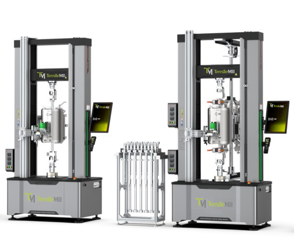
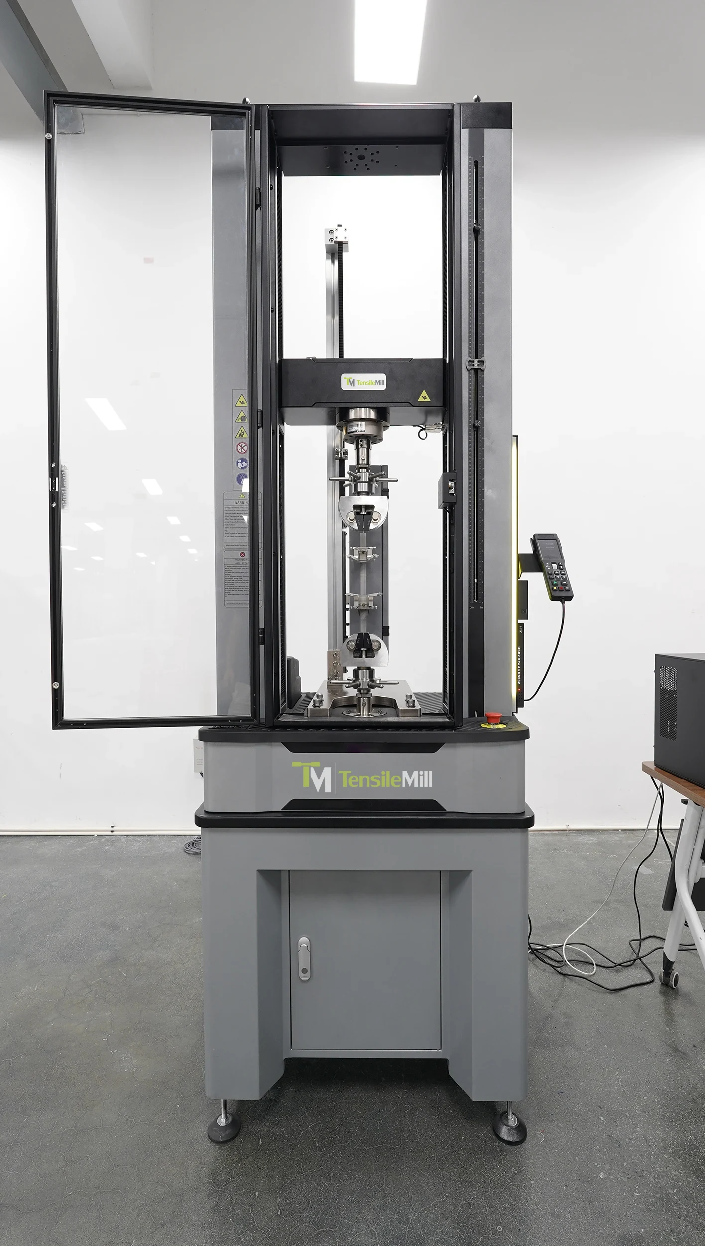
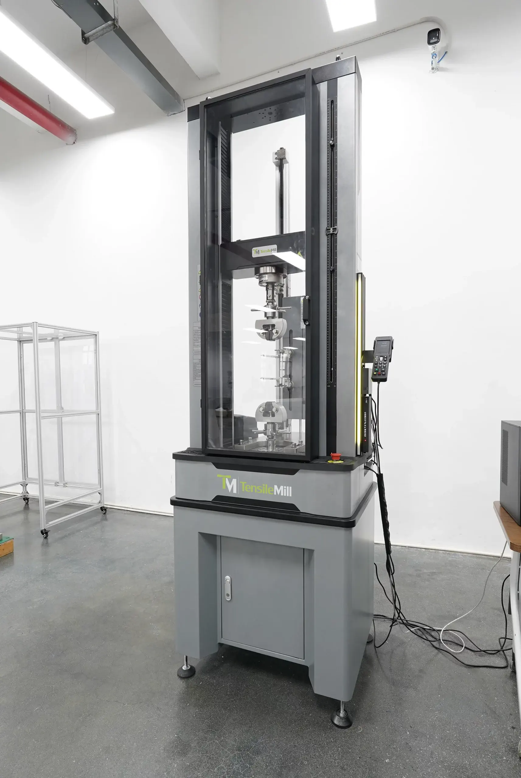
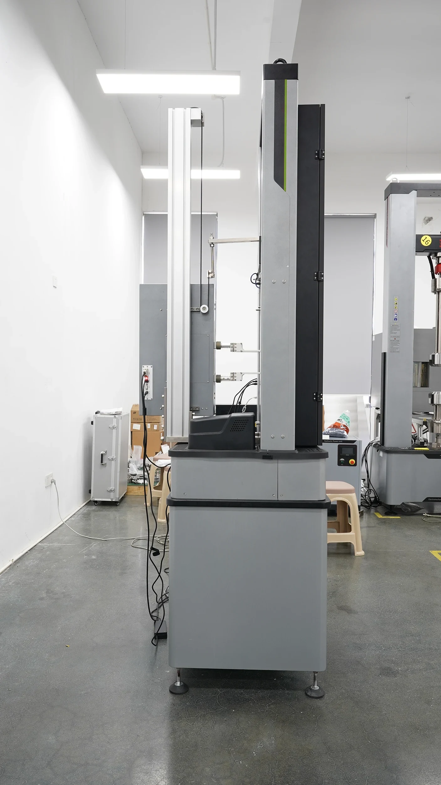
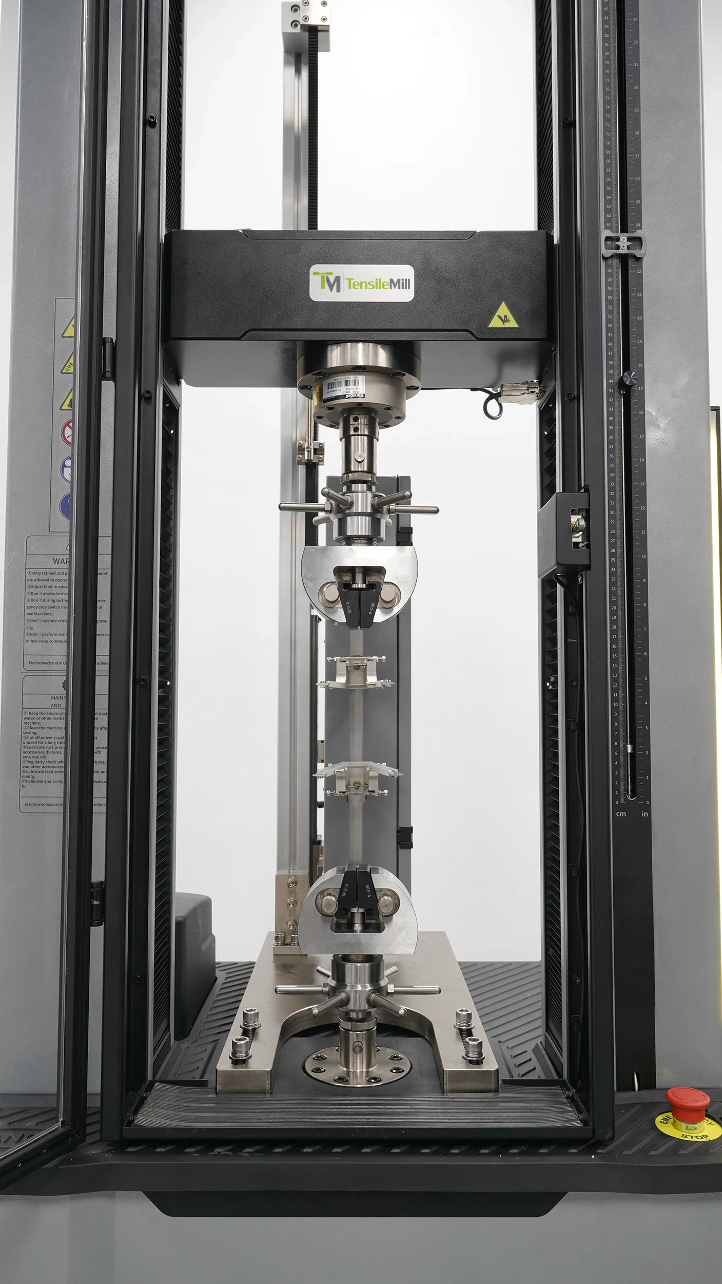
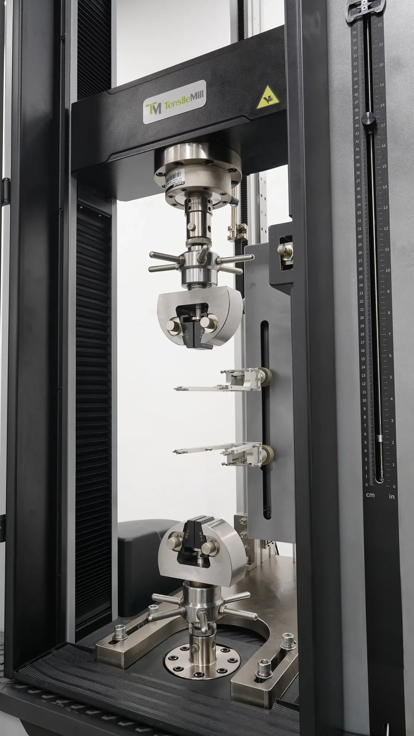
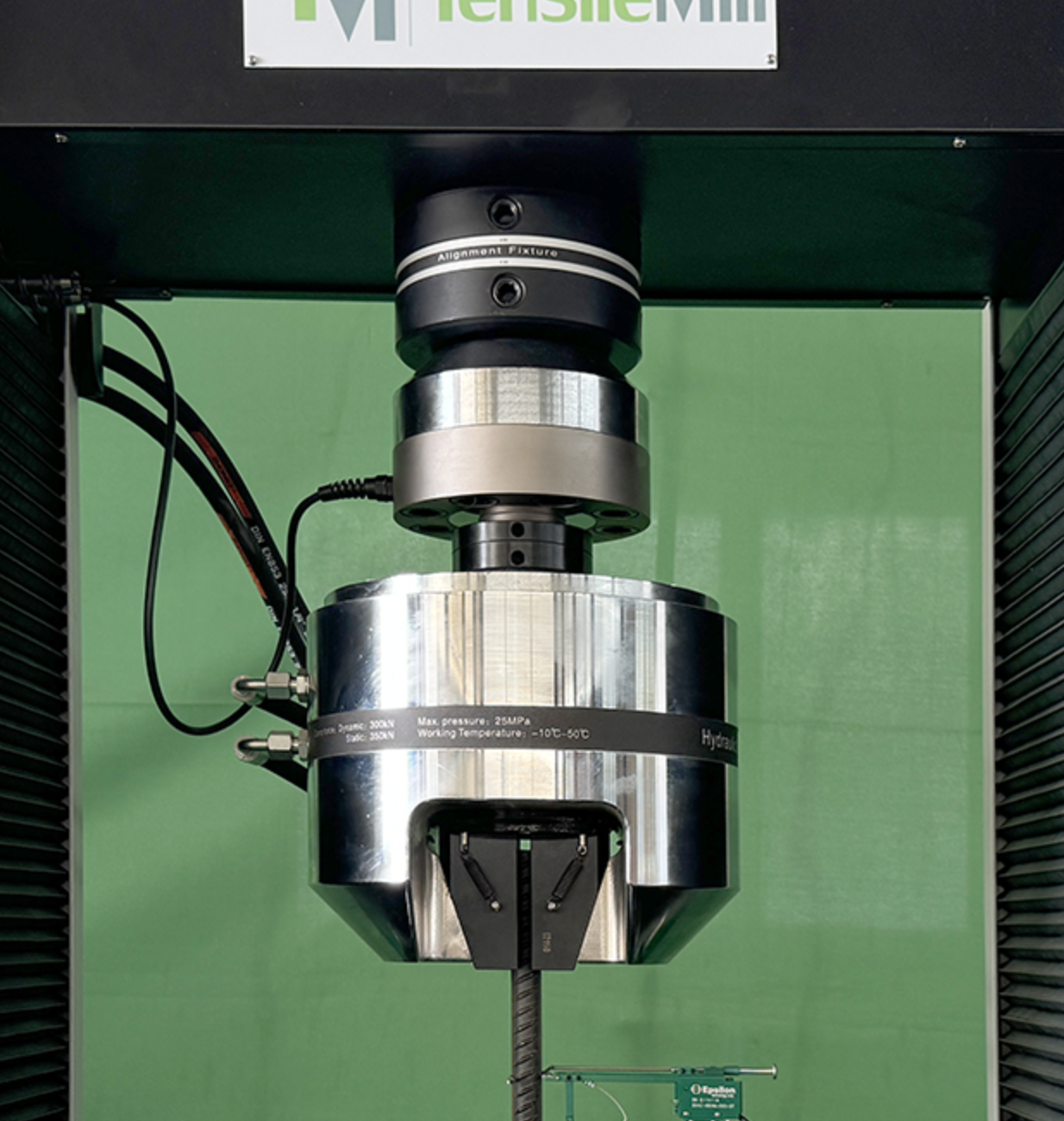
 - frame at 4m30s.jpg)
 - frame at 5m8s.jpg)
 - frame at 5m39s.jpg)
 - frame at 8m28s.jpg)
 - frame at 9m8s.jpg)
 - frame at 9m59s.jpg)