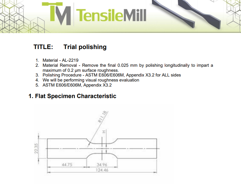
How Do I Set Polishing Parameters to Achieve Fatigue-Ready Surface Finish for ASTM E466 Specimens?
Achieving fatigue-ready surfaces requires removing circumferential tool marks and aligning the final scratch pattern with the specimen axis. On this system, begin with a conservative contact force of 1.1–3.4 lbf (5–15 N), a paper travel of 0.8–1.6 in/s (20–40 mm/s), and an active stroke that fully covers the gauge length, typically 0.20–11.0 in (5–280 mm). Use low rotation to prevent spiral crosshatching and keep heat input minimal.
Program a four-step abrasive sequence. For hardened steels and nickel alloys, a 240 → 400 → 600 → 800 grit progression removes turning marks efficiently. For aluminum and softer alloys, 320 → 600 → 800 → 1200 grit preserves geometry while improving finish. The equipment indexes through four papers automatically and maintains single-pass paper contact, which helps reduce residual stress. If stock removal lags, increase force toward 5.6–8.4 lbf (25–37 N), then drop to 1.1–2.2 lbf (5–10 N) for the finishing pass.
Verify with a profilometer. Many labs target 16–32 µin (0.4–0.8 µm) Ra for axial fatigue work, and ≤16 µin (≤0.4 µm) for high-strength alloys. Keep scratches strictly longitudinal, clean between grit steps, and avoid overheating. When preparing specimens for strain-controlled fatigue per ASTM E606, the same approach and finish thresholds are commonly applied. The machine supports paper speeds of 0.39–3.94 in/s (10–100 mm/s) and forces up to 11.2 lbf (50 N), allowing fine tuning for different materials and gauge lengths.
If you would like detailed specifications, model options, and footprint information, you can review everything on the
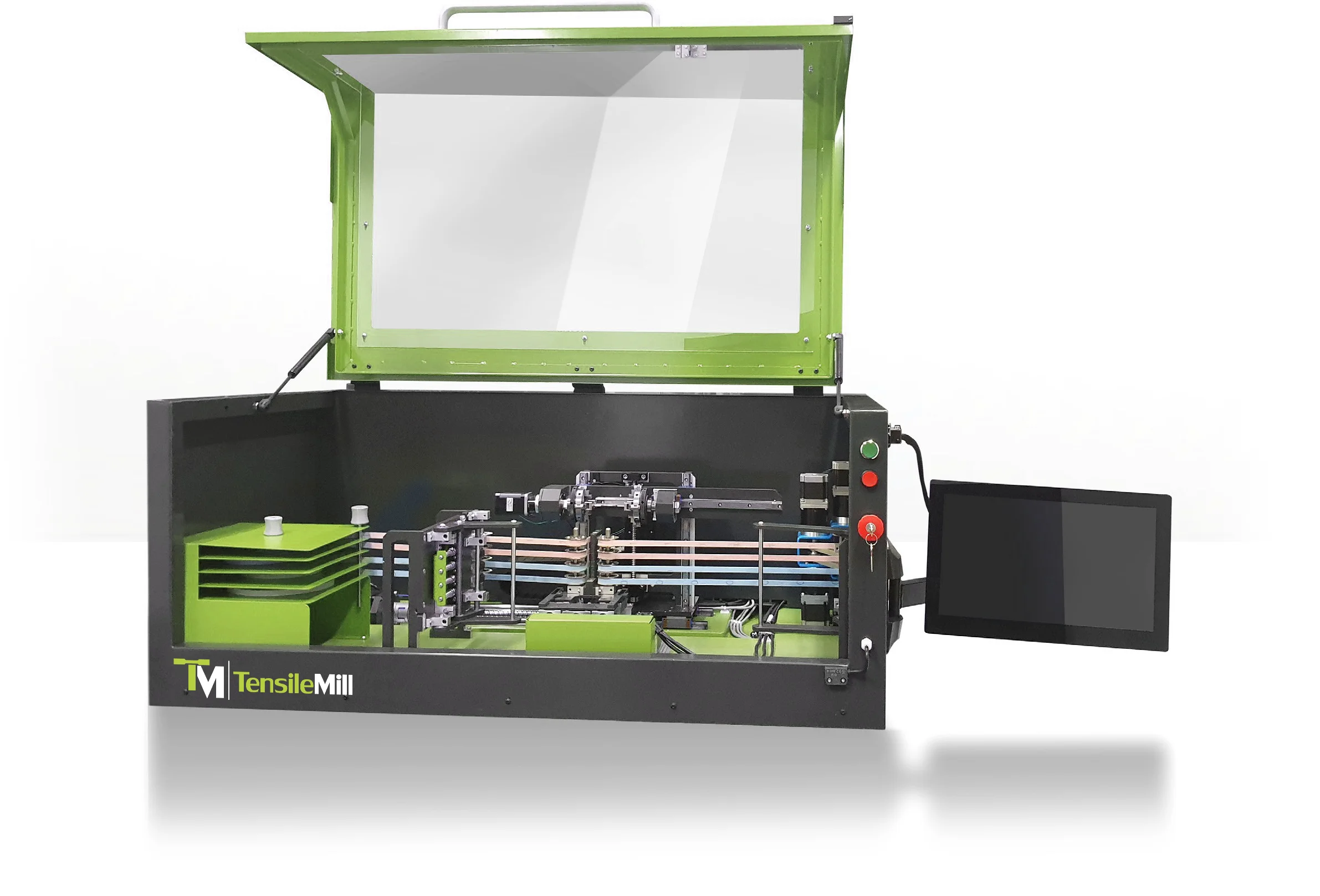
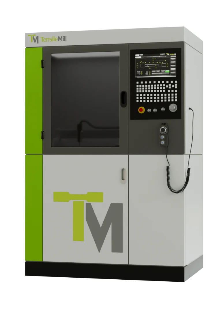
Automatic Longitudinal Polisher System equipment page.
Which Polishing Settings And Grit Sequence Produce Fatigue-Test-Ready Surfaces With A Longitudinal Polisher?
For fatigue-critical specimens, orient scratches along the loading axis and control heat and pressure. As a practical baseline, set the sandpaper force to 1.5–3.0 lbf (7–13 N) for aluminum and softer alloys, 3–6 lbf (13–27 N) for carbon and low-alloy steels, and 6–8 lbf (27–36 N) for hardened steels or nickel alloys. Use a travel speed near 1.0–2.0 in/s (25–50 mm/s) to maintain cool cutting. The equipment supports approximately 1.1–11.2 lbf (5–50 N) and 0.39–3.94 in/s (10–100 mm/s), so remain within those limits for process control. This approach helps meet the surface quality expectations typically associated with ASTM E466, ASTM E606, and EN 6072 fatigue preparation practices.
Start with 320–400 grit to remove machining marks, then progress to 600 and 800 grit. Add 1200 grit when a finer Ra is required, for example targeting about 32–63 µin (0.8–1.6 µm) on metals where notch sensitivity is a concern. Use fresh paper often so each surface zone contacts new abrasive only once, which limits residual stress.
Set the active polishing length to slightly exceed the gauge length, for example 1.10–1.20 in (28–30 mm) for a 1.00 in (25 mm) gauge, so transitions are outside the measurement zone. Rinse between grits with deionized water and alcohol, verify under 10× magnification, and record force, speed, and grit sequence for repeatability.
If you would like detailed specifications and setup ranges, you can review the
Automatic Longitudinal Polisher System on the product page.
How Do I Set Force, Speed, and Stroke for Standard-Compliant Longitudinal Polishing?
For fatigue and tensile specimens, longitudinal polishing removes machining marks while limiting residual stress. This equipment lets you program single-pass contact along the gauge length so the abrasive does not re-track the same area, which supports the preparation intent of ASTM E466 and ASTM E606, aligns with EN 6072 guidance, and fits NADCAP process-control expectations.
Typical starting parameters include normal force of 1.12–11.24 lbf (5–50 N), longitudinal abrasive speed of 0.39–3.94 in/s (10–100 mm/s) in 0.39 in/s (10 mm/s) increments, and active stroke of 0.20–11.02 in (5–280 mm). For carbon and low-alloy steels, begin around 3–6 lbf (13–27 N) at 0.79–1.57 in/s (20–40 mm/s) with a 6–8 in (150–200 mm) stroke. For aluminum, start near 1.5–3 lbf (7–13 N) at 0.39–0.79 in/s (10–20 mm/s). For titanium, use 3–5 lbf (13–22 N) and moderate speeds. Reduce force if you observe heat or discoloration, and lengthen the stroke when preparing longer gauge sections.
Use a progressive abrasive sequence such as 200, 400, 600, then 800 grit, taking advantage of the machine’s automatic four-media indexing. Between steps, clean the surface and cut force by about 25 percent for the final pass to minimize cold work. The system supports both round and flat specimens and stores repeatable recipes on the touchscreen for audit-ready documentation.
If you would like to review specifications and configuration options, you can explore the
Automatic Longitudinal Polisher System on the product page.
How Should I Set Longitudinal Polisher Parameters To Meet ASTM And NADCAP Surface Finish Targets?
Surface condition drives tensile and fatigue results. For machined tensile bars, many labs target Ra ≤ 63 µin (1.6 µm) within the reduced section, consistent with common practice under ASTM E8 and ISO 6892. For axial or strain-controlled fatigue work in line with ASTM E466 or ASTM E606, tighter finishes are typical, often Ra ≤ 16 µin (0.4 µm), with scratches strictly parallel to the specimen axis to limit stress concentrators and preserve geometry.
Set contact force conservatively, then increase only as needed for removal rate. As a starting point, use 1.1–3.0 lbf (5–13 N) for aluminum and softer alloys, 3–7 lbf (13–31 N) for most steels, and up to 11.2 lbf (50 N) for hard materials. Choose paper travel of 0.4–2.0 in/s (10–50 mm/s) to control heat on thin sections, with up to 3.9 in/s (100 mm/s) for robust geometries. Match stroke length to the gauge region, for example 2.0–4.0 in (50–100 mm) for subsize bars, or as long as 11.0 in (280 mm) when required. Use a grit sequence such as 240, 400, 600, 800, changing abrasives between passes and keeping a fresh track to avoid repeated contact on the same paper path.
Verify results with a calibrated profilometer, confirm all scratches are longitudinal, and record force, speed, stroke, and grit progression for traceability. These practices help align with NADCAP expectations for documented, repeatable surface preparation.
If you would like to review technical specifications and options, you can explore the
Automatic Longitudinal Polisher System equipment page for details on capacities, settings, and available models.
How Does an Automatic Longitudinal Polisher Improve Surface Integrity for ASTM E466 and E606 Fatigue Samples?
Longitudinal polishing aligns the scratch pattern with the specimen axis, which reduces circumferential micro-notches that can trigger early crack initiation in fatigue testing. By controlling contact pressure and ensuring one-time contact with any spot on the abrasive, the machine minimizes cold work and residual stress in the gauge section, supporting consistent results for ASTM E466, ASTM E606, and EN 6072 applications.
The equipment regulates polishing force across a usable range of about 1.1–11.2 lbf (5–50 N), with paper travel speeds near 0.39–3.94 in/s (10–100 mm/s) and an active polishing length that can be set from roughly 0.20–11.02 in (5–280 mm). These parameters let you match removal energy to material hardness, while the single-pass longitudinal motion limits localized heating and preserves geometry.
For repeatable finishes, use a progressive abrasive sequence, for example 220, 400, 600, then 800 grit. Begin at the low end of force, about 1.0–3.0 lbf (4.5–13.3 N), and moderate travel speed, around 1–2 in/s (25–50 mm/s). Increase only as needed to remove machining marks without altering diameter or thickness. Clean the gauge region between grits, verify the programmed active length covers the target gauge plus transitions, and complete with a light final pass to standardize surface texture across specimens.
If you would like to review model options and technical details, you can learn more on the
Automatic Longitudinal Polisher System product page.
When Should A Lab Move From Manual Polishing To An Automated Longitudinal System?
Move up when throughput and repeatability start to slip. If daily batches exceed 30–50 specimens, if fractures wander outside the gauge section, or if audit findings cite surface prep, a longitudinal system removes operator variance and aligns surface finish with ASTM E8/E8M and ISO 6892-1 requirements. For programs referencing DIN 50125, targeting about 250 µin Ra (6.3 µm) is common for machined metals, which often needs a controlled post-polish.
An automated longitudinal polisher drives the abrasive along the loading axis to avoid transverse scratches, then repeats the same cycle every time. Typical controllable settings include active length of 0.20–11.02 in (5–280 mm), belt speed of 0.39–3.94 in/s (10–100 mm/s), and polishing force of about 1.1–11.2 lbf (5–50 N). Many systems run up to four abrasive grades in sequence, which helps high-volume and NADCAP workflows.
For setup, begin with a 240→400→600→800 grit sequence. Start near 1.6–2.0 in/s (40–50 mm/s) and 3–6 lbf (13–27 N), polish only the gauge length, and keep the part below 140 F (60 C). Verify first-article breaks in the gauge section and adjust force or grit steps if elongation scatter remains.
If you would like to review settings and fixturing options, you can explore details on the
Automatic Longitudinal Polisher System product page.
Why Polish Tensile Specimens After Machining For ASTM E8 And ISO 6892 Compliance?
Scratches, burrs, and cold-worked edges act like tiny notches that raise local stress. They can shift fracture outside the intended region and depress elongation or yield readings. ASTM E8 and ISO 6892 accept results only when fracture occurs within the middle third of the gauge length. For a 2 in (50 mm) gauge, that means the central 0.67 in (17 mm). Skipping polishing often produces off-gage breaks or scattered data that fails internal quality checks.
Target the gauge section and edges. After blanking, punching, waterjet, or laser cutting, remove burrs and any smeared material. Align the final scratch pattern with the loading axis, avoid transverse marks, and keep contact pressure steady so heat does not alter hardness or geometry. Recheck width and thickness after polishing; many labs limit stock removal to under 0.002 in (0.05 mm) per side to hold dimensions while cleaning the surface.
High-volume labs typically move to longitudinal equipment that drives the abrasive along the specimen length, supports multiple grit steps, and applies controlled force for repeatable results across batches and operators.
If you would like to review automating this step, you can explore details on the
Automatic Longitudinal Polisher System product page.
How Does Specimen Polishing Affect Tensile Test Accuracy And ASTM E8 Compliance?
Surface condition governs stress flow in the gauge. Burrs, torn edges, and cross-scratches act as notches that shift fracture out of the gauge or depress elongation. ASTM E8 and ISO 6892 call for a gauge region free of visible defects; many labs target surface roughness at or below 250 µin Ra (6.3 µm), with finer finishes for high strength or low ductility alloys.
A practical workflow is to deburr and break sharp corners lightly, about 0.005 to 0.010 in (0.13 to 0.25 mm), then polish along the loading axis. Move through 240, 400, 600, and 800 grit, checking dimensions after each step. Keep temperature low to avoid altering thin sections. For repeatable pressure, many operators run light contact at 1 to 3 lbf (5 to 13 N) during fine passes and avoid exceeding 10 to 11 lbf (45 to 50 N) on thin coupons.
High-throughput labs favor longitudinal polishing that keeps scratches parallel and avoids transverse scoring. The TensilePolish system provides adjustable active length from 0.20 to 11.0 in (5 to 280 mm), abrasive speed from 0.39 to 3.94 in/s (10 to 100 mm/s), and controllable force from 1.1 to 11.2 lbf (5 to 50 N). Multi-grit sequencing in one cycle shortens setup and tightens lot-to-lot consistency for flat and round specimens.
If you would like to review automated polishing controls and sizing options, you can explore details on the
TensilePolish Automatic Longitudinal Polisher System product page.
Why Does Surface Finish On Tensile Specimens Matter For ASTM E8 And ISO 6892 Compliance?
Surface condition directly affects fracture location and scatter in yield, tensile strength, and elongation. Machining marks and burrs behave like notches, raising local stress and causing breaks outside the gauge length. ASTM E8/E8M and ISO 6892-1 call for removal of visible defects. Many labs target 250 μin Ra (6.3 μm) or better for general metals, and 32 to 63 μin Ra (0.8 to 1.6 μm) for high strength alloys.
Polish along the loading axis to avoid transverse scratches. Use a progressive grit sequence, for example 240, 400, 600, then 800 or 1200. Keep normal force low, roughly 0.25 to 2.5 lbf (1 to 11 N), and watch temperature to prevent tempering or smearing. Blend edges on flat coupons by about 0.005 to 0.010 in (0.13 to 0.25 mm). Verify finish with 10x visual checks and confirm dimensions before testing or mounting extensometers or DIC patterns.
For repetitive work, a longitudinal polisher holds orientation and repeats settings across batches. The TensileMill longitudinal polishing system supports polishing lengths around 0.20 to 11.0 in (5 to 280 mm) and abrasive speeds near 0.39 to 3.94 in/s (10 to 100 mm/s) with multi grit sequencing.
If you would like to review settings and fixture options, you can explore details on the
Automatic Longitudinal Polisher System product page.
Why Does Polishing Matter For Valid Tensile Test Results?
Surface defects act as stress raisers. A scratch across the gauge, a burr at the edge, or a heat-tinted band from machining can shift strain away from the center and trigger early fracture outside the gauge length. ASTM E8/E8M and ISO 6892-1 call for a clean, defect-free gauge section and for results to be rejected when fracture occurs at a defect or outside the gauge. A polished gauge produces a more uniform stress field, steadier extensometer tracking, and tighter scatter across repeats.
In practice, operators deburr and lightly break edges, then remove the cold-worked layer from sheared blanks with a light grind of about 0.002–0.004 in (0.05–0.10 mm). Abrasives are stepped finer with the scratch pattern aligned with the load direction. Many labs target the gauge at roughly 63–125 µin Ra (1.6–3.2 µm), and for high-strength alloys push toward 32 µin Ra (0.8 µm). Keep temperatures low and verify final dimensions after polishing.
For repeatable work at volume, longitudinal polishing equipment maintains a controlled travel speed near 0.4–4.0 in/s (10–100 mm/s) with regulated force around 1–11 lbf (5–50 N). This produces lengthwise scratches, reduces transverse marks, and supports consistent failure within the gauge.
If repeatable lengthwise surface preparation is a priority, you can explore details for the
Automatic Longitudinal Polisher System on the product page.
How Should Forging Labs Size a UTM and Specimen Preparation Setup for Tensile QA?
Start with load. Multiply the highest expected ultimate tensile strength by the largest test cross-section you plan to machine, then add a safety margin for strain hardening and grip friction. Example: a 0.505 in (12.83 mm) round per ASTM E8 has about 0.200 in² (129 mm²) area. At 150 ksi (1,034 MPa), peak load is roughly 30,000 lbf (133 kN). A 50 kip (222 kN) frame handles most steels. For oversized coupons or subcomponent pulls, plan for 135 kip (600 kN) to 225 kip (1,000 kN) hydraulic frames.
Specimen preparation drives repeatability. A CNC system that holds dimensional tolerance to ±0.0003 in (±0.008 mm) and machines up to 60 HRC cuts down rework and out-of-spec blanks. For surface integrity, a longitudinal polisher set for length, speed, and pressure removes circumferential tool marks and helps maintain finishes near 32 µin Ra (0.8 µm) before testing.
During testing, follow ASTM E8 or ISO 6892-1 for gauge length, speed or strain-rate control, and extensometer use, commonly 2 in (50 mm). Record heat number, orientation, and heat-treat batch with every pull so outliers can be traced to forging or thermal variables, not preparation artifacts.
You can review frame capacities and control options on the
Tensile Testing Equipment equipment page.
What Gauge Surface Finish Is Recommended For Tensile Specimens, And How Do Labs Achieve It?
ASTM E8/E8M and ISO 6892 call for smooth, burr-free gauge surfaces, but they do not prescribe a specific roughness value. Many labs target Ra ≤ 80 µin (2.0 µm) for metallic specimens to cut the risk of micro-notch initiation, extensometer slip, and premature shoulder breaks.
For flat coupons, program a climb-mill finish pass with 0.002–0.004 in (0.05–0.10 mm) radial stock, a stable feed, and sharp carbide to suppress chatter. For round bars, use a light final turning pass of 0.001–0.003 in (0.03–0.08 mm) per side at 200–400 sfm (61–122 m/min) with coolant. Keep tool marks parallel to the loading axis and avoid cross-scratches in the gauge.
After machining, deburr with a single light stroke and polish lengthwise. A 3-step sequence, for example 400, 600, then 800 grit, typically delivers Ra 32–63 µin (0.8–1.6 µm). Automated longitudinal polishing maintains directionality and low induced stress, with controlled force of 1–11 lbf (5–50 N) and an active stroke of 0.2–11.0 in (5–280 mm). Record the achieved Ra and surface method in the test file when reporting to ASTM E8 or ISO 6892.
If you would like to review polishing parameters and fixturing, you can explore details on the
Automatic Longitudinal Polisher System product page.
How Should Surface Finish and Edge Quality Be Controlled for Reliable ASTM E8 and ISO 6892 Tensile Results?
Target a gauge-section roughness of 80 µin Ra (2 µm) or finer for most metals. For high-strength or brittle alloys, work toward 32–63 µin Ra (0.8–1.6 µm). Create a dedicated finish pass of about 0.005 in (0.13 mm) with climb milling and coolant, then clean the gauge section with acetone. Extensometer contact pads should be flat within about 0.001 in (0.025 mm) over the contact length.
Protect the profile. Break sharp edges lightly, about 0.005–0.010 in (0.13–0.25 mm), avoiding a large chamfer that reduces area. Inspect the entire perimeter at 10× to catch nicks and micro-notches. If blanks are cut by waterjet or EDM, leave 0.020–0.040 in (0.5–1.0 mm) stock and remove striations or recast with a final mill or grind. After laser cutting, remove the heat-affected layer by grinding 0.004–0.008 in (0.10–0.20 mm) from the gauge walls.
Record finish, edge break, and inspection magnification with each lot. Verify final dimensions per ASTM E8 or ISO 6892 drawings, and keep grip faces clean to prevent slip that masks surface-related problems.
If you want controlled Ra and scratch direction without changing geometry, you can explore details on the
Automatic Longitudinal Polisher System equipment page.
How Do Labs Plan An In-House Tensile Specimen Preparation Setup That Meets ASTM And ISO Requirements?
Start with your standards and geometry library. For metals, ASTM E8 subsize and full-size choices often use 2.0 in (50 mm) or 1.0 in (25 mm) gage lengths; plastics commonly follow ISO 527 geometries. A software-driven workflow that lets operators pick a template, then locks critical dimensions and shoulder radii, reduces programming mistakes and shortens onboarding for new staff.
Match equipment to stock. Use a flat-specimen milling system for dog-bone blanks from plate or sheet, and a round-specimen CNC lathe for bars and rods. For consistent finish, leave about 0.020 in (0.50 mm) per side for a final pass near 0.008 in (0.20 mm). Target a surface roughness near 63 µin (1.6 µm) or better; if tool marks remain, a longitudinal polisher helps clean the gauge section without rounding edges.
Plan the workflow details. Keep dedicated fixtures that center the blank on the machine axis and prevent tilt. Stage duplicate cutters and inserts, and track tool life by part count instead of time. Use workholding that clamps outside the shoulder region so the gage section is untouched. Maintain a small kit of consumables, including end mills, lathe inserts, jaw pads, and polishing media, to avoid stoppages.
If you would like to review sample-prep options for your lab, you can connect with our team on the
Contact Us page.
How Does a Single-Vendor Tensile Testing Workflow Improve Compliance and Throughput?
A single-vendor workflow ties specimen preparation, polishing, and tensile testing into one chain. Operators work from standard libraries aligned to ASTM and ISO geometries, which cuts programming steps and reduces mismatches between machined dimensions and test fixtures. Lead time drops because blanks move directly from the mill or lathe to the tester, while one support group handles installation, calibration, and training.
Typical chain: flat milling or round turning to the specified gauge and fillet radii, optional longitudinal polish, then testing on a UTM with matched grips and an extensometer. For metals per ASTM E8, a common gauge length is 2 in (50 mm). For plastics per ASTM D638 or ISO 527, Type I and 1A specimens use 2.0 in (50 mm) gauge length. Size the frame to at least twice the predicted failure load, for example 22 kip (100 kN) for many steels.
On the floor, watch details that affect repeatability. Keep gauge length temperature under 150 F (65 C) during machining to avoid local property changes. Inspect cutters every 25 to 50 parts and adjust feed to prevent chatter that raises surface stress. Use wedge or pneumatic grips with serrations matched to hardness, verify alignment per ASTM E1012, and keep spare jaws and sharp inserts on hand to avoid mid-run delays.
If you would like to discuss your workflow, you can connect with our team on the
Contact Us page.
What Surface Finish And Longitudinal Polishing Steps Improve Aerospace Tensile Test Repeatability?
For metallic spacecraft alloys, surface defects act as stress risers that shift the failure location. Labs typically target a gage-section finish of Ra 16–32 µin (0.4–0.8 µm). Machine and polish tracks must run parallel to the load axis. Hold gage length to 2.0 in (50 mm) with diameter or width variation under ±0.001 in (±0.025 mm) across the gage. A small shoulder fillet, about 0.02–0.04 in (0.5–1.0 mm), helps avoid localized necking at the transition.
A practical longitudinal sequence is 320 → 600 → 800 → 1200 SiC, using light force of about 2–10 lbf (9–44 N). For round specimens, rotate slowly, roughly 60–120 rpm (1–2 rps), and move along an active length near 2–10 in (50–250 mm). Use water-based coolant and keep temperature rise below 20 °F (11 °C) to avoid altering microstructure or residual stress. Measure finish with a contact profilometer using a 0.03 in (0.8 mm) cutoff.
Verify alignment and finish before testing. Under ASTM E8 and ASTM E21, the gage section should be smooth and free of nicks with machining lines parallel to the axis. Many aerospace programs also mirror fatigue-prep practice from ASTM E466 and E606, which favors a uniform longitudinal finish to reduce scatter in elongation and UTS.
You can review polishing workflow details on the
Automatic Longitudinal Polisher System product page.
How Does Longitudinal Polishing Improve Aerospace Tensile Test Repeatability?
Scratches that cross the load axis act like tiny notches, which can inflate measured yield and suppress elongation. On high-strength aerospace alloys, a poor scratch pattern can shift ultimate strength by 2–5 ksi (14–34 MPa). Longitudinal polishing orients the finish with the load, reducing transverse stress raisers so the fracture reflects material behavior, not surface damage. Many aerospace labs target a gauge-section finish near Ra 16–32 µin (0.4–0.8 µm) for consistent tensile results.
With an automatic longitudinal system, set a progressive sequence, for example 320 → 600 → 1200 grit, then verify directionality under 10× magnification. Use a light, steady contact force around 3–8 lbf (13–36 N) and a paper travel speed near 0.4–1.6 in/s (10–40 mm/s). Keep the active stroke at least 0.5 in (13 mm) beyond the gauge length at each end to avoid edge ridges. Control heat, keeping the surface under 150°F (65°C), and clean with high-purity IPA immediately before testing.
For metals, ASTM E8/E8M requires a gauge free of nicks and laps. Fatigue-ready finishes commonly reference ASTM E466, ASTM E606, and EN 6072, which favor longitudinal texture. NADCAP audits typically review media grade, force, speed, and lot traceability, so log these setpoints and retain a surface-finish record.
If you would like to review setup options, you can explore details on the
Automatic Longitudinal Polisher System equipment page.
What Final Polishing And Inspection Steps Reduce Tensile Specimen Rejections?
Finish the gauge section with a longitudinal polish along the loading axis to avoid circumferential scratch lines. A practical sequence is 600-grit, then 1200-grit, then a fine diamond compound to reach Ra ≤ 4 µin (0.10 µm). Keep contact pressure low and use clean coolant to limit embedded grit and residual grinding stress. For metals, follow polishing practices consistent with ASTM E407. For composite coupons, avoid fiber pull-out by using lighter passes and fresh abrasives.
Verify dimensions before the UTM. Measure thickness and width at three locations with a micrometer that reads 0.0005 in (0.013 mm) or better, and check gauge length tolerance within ±0.002 in (±0.05 mm) per the relevant standard such as ASTM E8 for metals or ASTM D3039 for composites. Inspect the transition regions for machining marks or burrs using 10x magnification. A quick cotton-swab pass often reveals raised edges that a visual check can miss. If available, confirm straightness and parallelism with a CMM to about ±0.0008 in (±0.02 mm).
High-throughput labs gain repeatable finishes by using an automatic longitudinal polisher with controlled stroke, speed, and force, which is especially useful for fatigue coupons prepared to ASTM E466 or ASTM E606.
If you would like to review automation features and finish controls, you can explore details for the
Automatic Longitudinal Polisher System on the equipment page.
How Does a Longitudinal Polisher Improve Tensile Specimen Surface Quality and Test Repeatability?
Longitudinal polishing removes circumferential tool marks from machining and lays the scratch pattern along the load axis. This reduces local notch effects in the gauge section and helps stabilize results for tensile per ASTM E8/E8M and for fatigue coupons prepared for ASTM E466 or E606. An automatic unit such as the TensilePolish GR04 keeps the contact path uniform and repeats the same passes specimen after specimen.
In practice, set the active polishing length to cover the full gauge, for example 0.2–11.0 in (5–280 mm). Begin with light pressure, about 1.1–3.4 lbf (5–15 N) on soft alloys, then increase carefully for harder materials without exceeding 11.2 lbf (50 N). A traverse speed around 0.4–1.6 in/s (10–40 mm/s) gives good control, within the machine’s 0.39–3.94 in/s (10–100 mm/s) range. Use a grit sequence such as 240, 400, 600, 800 and advance only when the previous scratch pattern is fully removed.
Watch temperature and loading. If the paper glazes, reduce force slightly or increase traverse speed, then clean or index the abrasive. For round bars, keep rotation slow and contact centered to avoid flats. For flat coupons, verify parallel clamping so the gauge stays square to the belt. These habits cut scatter in yield, elongation, and fatigue life.
You can review specifications and model options on the
Automatic Longitudinal Polisher System product page.
How Should I Set Force, Speed, and Grit on an Automatic Longitudinal Polisher for ASTM E8 and Fatigue Specimens?
Start with fixturing. Clamp the blank so the gauge axis is parallel to the polishing stroke, then set the active length to cover the full gauge plus about 0.5 in (13 mm) into the shoulders. Longitudinal scratches reduce off-axis stress risers, which aligns with specimen preparation practices in ASTM E8/E8M and EN 6072.
Typical starting parameters on a GR04 system are 1 to 3 lbf (5 to 13 N) for softer alloys like aluminum and 4 to 8 lbf (18 to 36 N) for hardened steels. Use 1.0 to 2.0 in/s (25 to 50 mm/s) for coarse grits, then slow to 0.4 to 0.8 in/s (10 to 20 mm/s) for the final pass. A common grit ladder is 240 → 400 → 600 → 800, with an optional 1000 to 1200 final step for fatigue work. Keep material removal minimal, typically under 0.001 in (0.025 mm) per side.
Verify results with a profilometer and a quick mic check in the gauge. Many labs target 16 to 32 µin Ra (0.4 to 0.8 µm) for fatigue per internal procedures under ASTM E466 or E606 programs. The GR04’s ranges, 1 to 11 lbf (5 to 50 N), 0.4 to 4.0 in/s (10 to 100 mm/s), and 0.2 to 11.0 in (5 to 280 mm), support these settings along with automatic four-grit sequencing.
If you would like parameter ranges and fixture options in one place, you can review the
Automatic Longitudinal Polisher System on the product page.
How Does an Automatic Longitudinal Polisher Improve Tensile and Fatigue Specimen Preparation?
Longitudinal polishing removes circumferential tool marks from turning or milling that act as stress concentrators. By driving the abrasive along the specimen axis, the scratch lay follows the loading direction used in ASTM E8/E8M tension and in axial fatigue work under ASTM E466 or E606, which reduces scatter from early crack initiation and helps maintain uniform strain fields.
In practice, the operator sets force and travel to match alloy hardness and geometry. Systems like the TensilePolish GR04 allow about 1.1–11.2 lbf (5–50 N) contact force, 0.39–3.94 in/s (10–100 mm/s) longitudinal speed, and 0.20–11.02 in (5–280 mm) active length. Start with a coarse grit, then step through four programmed grits, for example 200 → 400 → 600 → 800, while keeping consistent force to avoid taper or edge rounding. Automatic grit changes and in-cycle cleaning keep debris from embedding. Verify progress with a profilometer, wipe the gauge section between steps, and avoid heat buildup.
For general tensile work, many labs target about 32–16 µin Ra (0.8–0.4 µm) with smooth fillet blends. For axial fatigue coupons, a finer 16–8 µin Ra (0.4–0.2 µm) and strictly longitudinal lay are common. Record parameters and results for audits such as NADCAP and for EN 6072 preparation checks.
If you would like to review specifications and model options, you can explore details on the
Automatic Longitudinal Polisher System product page.
How Do I Set Force, Speed, And Grit On An Automatic Longitudinal Polisher For Fatigue-Critical Tensile Specimens?
Start with a conservative force and a coarse grit, then step finer. For sub-size or thin sections, begin around 1–3 lbf (5–13 N). For larger gage sections, work in the 5–8 lbf (22–36 N) range. Use a straight grit sequence such as 240 → 400 → 600 → 800, and keep the abrasive lay parallel to the loading axis for ASTM E466 or E606 fatigue work. If the specimen starts to crown, reduce force and verify full-length contact along the gage.
Set longitudinal traverse near 0.4–1.6 in/s (10–40 mm/s) to limit heat while removing machining marks. Tough alloys can tolerate 2.0–3.9 in/s (50–100 mm/s) with coolant. Match the active polishing length to the gage length and adjacent blend, from 0.2–11.0 in (5–280 mm), and overlap each end by about 0.04–0.12 in (1–3 mm) to avoid step lines.
Before testing, confirm surface lay and roughness. Many labs target about 16–32 µin Ra (0.4–0.8 µm) for general tensile and 8–16 µin Ra (0.2–0.4 µm) for fatigue. Inspect under bright, raking light, then wipe with solvent to remove embedded grit.
If you would like to review control ranges and model options, you can explore details for the
Automatic Longitudinal Polisher System on the product page.
How Do I Set Force, Speed, and Grit Sequence on an Automatic Longitudinal Polisher for Tensile Specimens?
Start by matching force and travel speed to the alloy and geometry. A practical window on a longitudinal polisher is about 1.1–11.2 lbf (5–50 N) of contact force. Use the low end for aluminum and thin sections to avoid smearing, and the mid range for alloy steels and nickel alloys. Pair this with 0.4–3.9 in/s (10–100 mm/s) longitudinal speed. If cutting marks persist, hold force and reduce speed; if the surface hazes, lower force or increase speed. Keep rotation steady to avoid cross-hatching.
Program a consistent grit ladder and let the automatic changer do the work. A common sequence is 240 → 400 → 600 → 800 grit. At each stage, dwell until the previous scratch pattern is fully replaced, then trigger an automatic paper refresh or cleaning pass. For hard materials, add an intermediate grit or extend dwell; for soft metals, use lighter force and shorter dwell to prevent pull-out.
Set active polishing length to cover the gauge section plus small margins, for example gauge length plus 0.2–0.4 in (5–10 mm) per side, within the typical 0.20–11.0 in (5–280 mm) range. Longitudinal finishing supports specimen preparation aligned with EN 6072 and is often chosen for fatigue programs per ASTM E466 and ASTM E606.
You can review parameter ranges and configuration details on the
Automatic Longitudinal Polisher System product page.