Why should I choose TensileMill CNC MINI as my flat tensile specimen preparation machine?
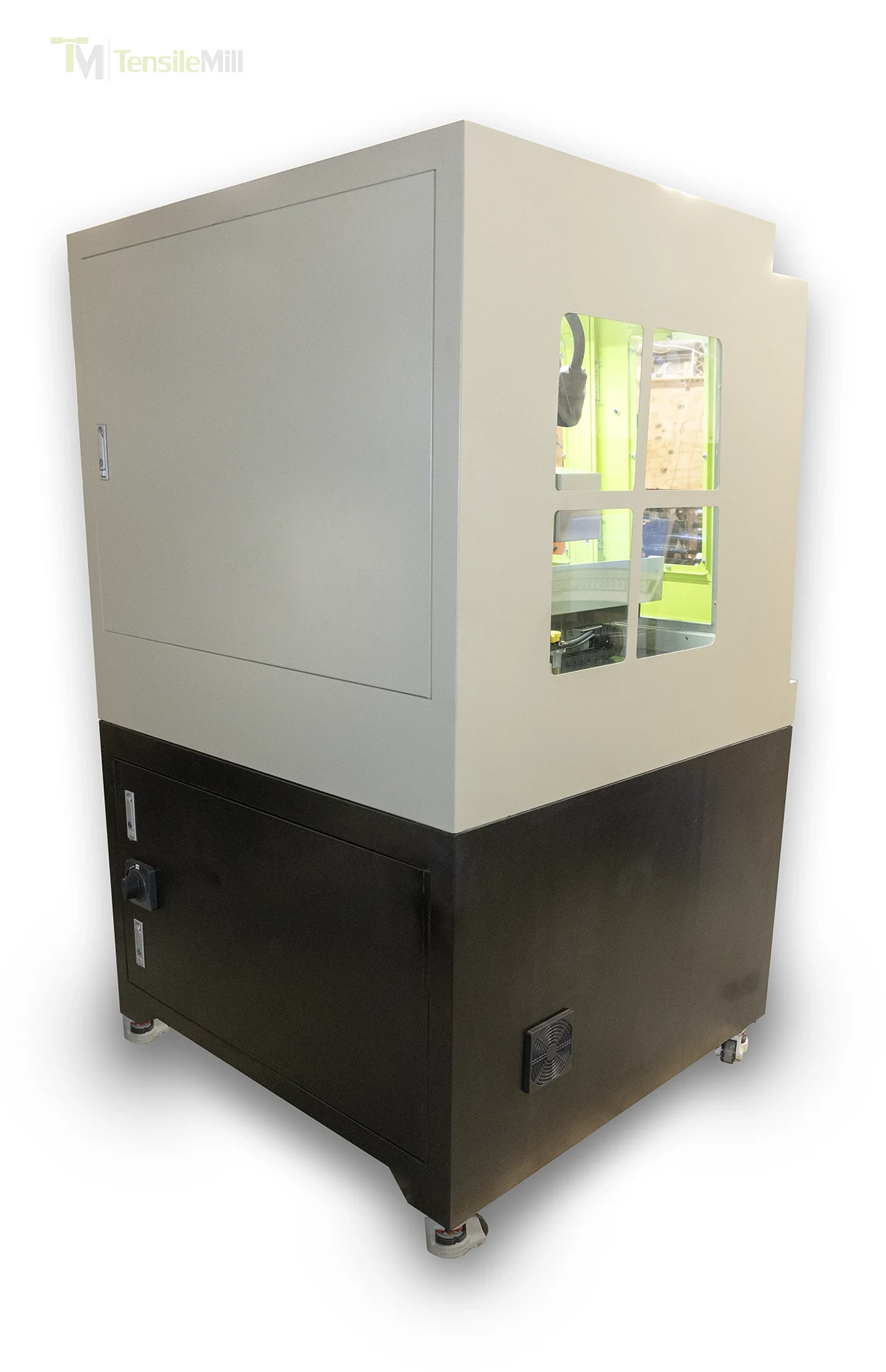
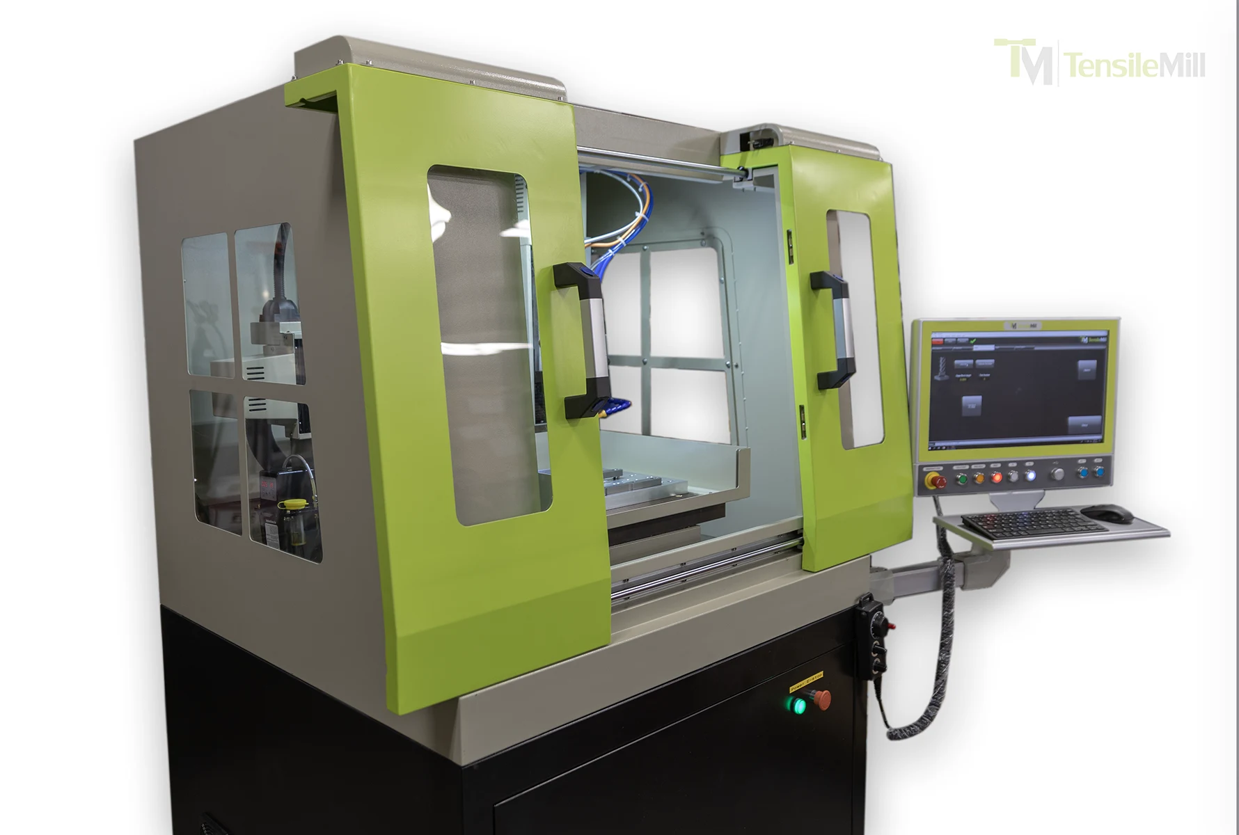
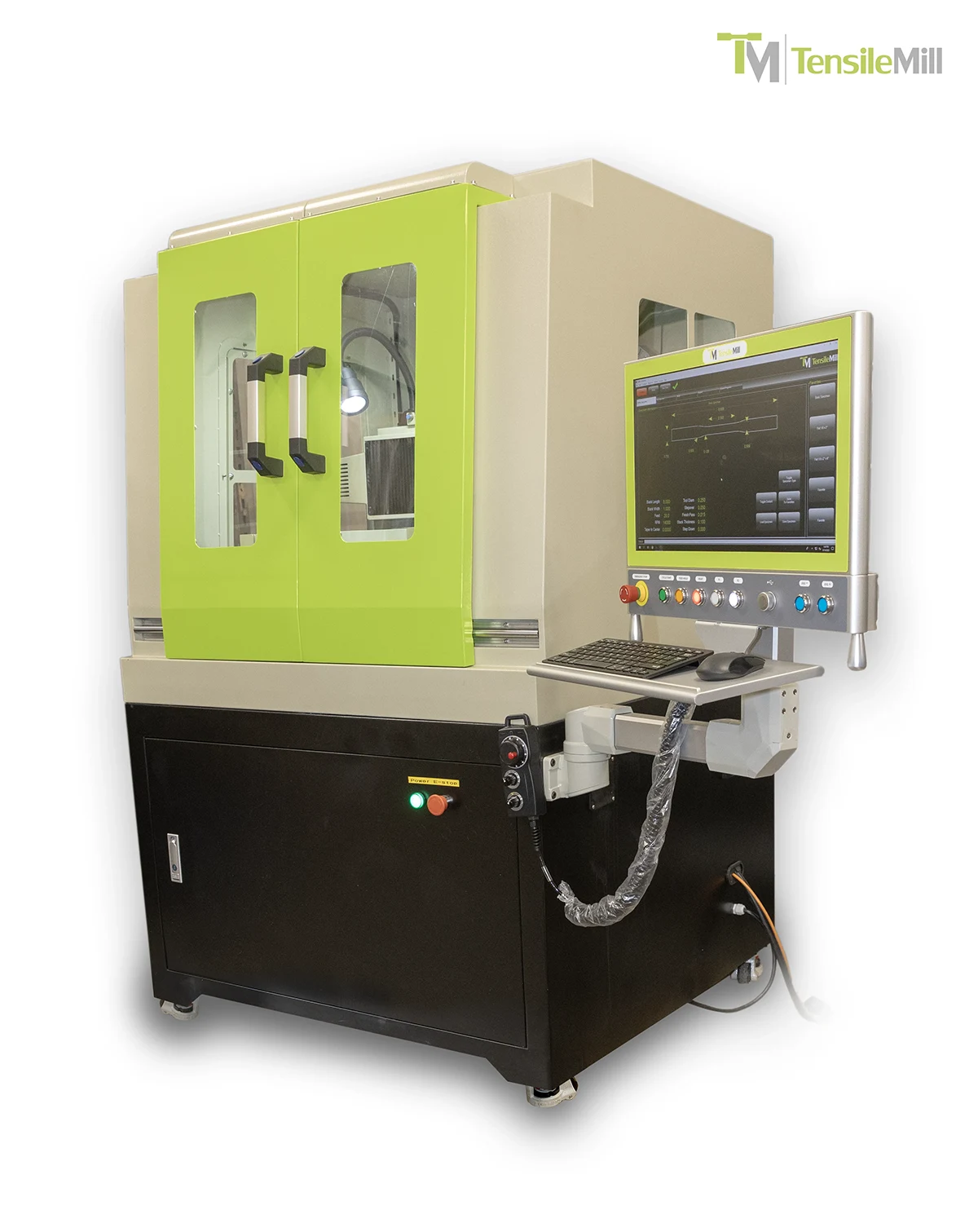
TensileMill CNC MINI is a compact, high-speed flat tensile specimen preparation system designed for labs that need CNC-level precision without the footprint and complexity of a full machining center. It is ideal for preparing tensile specimens up to approximately 15" × 2" × 0.5" thick (about 380 × 50 × 12.5 mm) from plates up to around 14" × 14" (355 × 355 mm), covering the vast majority of ASTM and ISO flat coupon formats.
Key reasons engineers and QC managers choose the MINI:
Broad material capability – from soft metals like copper and aluminum to high-strength steels, titanium, Inconel, as well as rubber, plastics, and composite panels.
Turnkey tensile workflow – preconfigured tensile milling software, base fixtures, and tooling designed specifically for ASTM E8, ASTM A370, ISO 6892, DIN, JIS and related standards.
Production-ready table and travel – 400 mm × 400 mm × 200 mm working area (approx. 15.75" × 15.75" × 7.87") to comfortably handle multi-up coupon layouts or thicker starting plates.
TensileMill CNC
Upgrade path – optional Carbon CNC package unlocks full G-code machining for fixtures, R&D coupons, and auxiliary parts.
Typical scenarios where the MINI shines:
A mid-volume QC lab running dozens to hundreds of ASTM E8 specimens per month, wanting to eliminate outsourcing and long lead times.
A metallurgical or R&D lab cutting test coupons from advanced alloys (e.g., Inconel) where dimensional consistency and edge quality directly affect test results.
An educational or corporate training facility looking for a user-friendly CNC tensile mill that non-machinists can operate through a guided interface.
Because the MINI is supplied as a turnkey system, you get fixtures, tensile software, and recommended tooling out of the box, along with support for configuration and training. That combination shortens your time to first specimen and maximizes long-term value.
To explore capabilities, specimen compatibility, and available configurations, visit the
TensileMill CNC MINI page.
What kind of after-sales support can I expect for the TensileMill CNC MINI?
With the TensileMill CNC MINI, after-sales support is structured to cover the entire lifecycle of your flat tensile specimen preparation system—from first installation through years of production use.
You can expect:
Pre-installation consultation – help choosing the right configuration, fixtures, and software options for your standards and sample sizes.
Guided installation and commissioning – remote guidance or on-site assistance to bring the machine into service correctly.
Hands-on operator training – focused on TensileSoft, fixture loading, safe operation, and best practices for coupon consistency.
Ongoing technical support – via phone, email, and online ticket system for troubleshooting, process optimization, and software questions.
Service plans and PM programs – preventive maintenance options to extend machine life and reduce unplanned downtime.
In practical terms, that means when a lab manager adds new staff, changes materials, or introduces a new standard, they can reach back to TensileMill for refresher training, fixture guidance, and updated process recommendations.
For details on commissioning, operator training, and long-term support programs, connect through the
TensileMill CNC MINI product page.
What is the lead-time for the TensileMill CNC MINI - Compact Flat Tensile Specimen Preparation Machine?
Lead times for the TensileMill CNC MINI typically range from about 3 to 5 months, with many orders shipping closer to the 3-month mark depending on configuration, demand, and region.
Several factors influence your specific lead time:
Machine configuration – standard MINI units with common fixtures generally ship sooner; customized fixtures or automation options may add time.
Regional logistics – shipping, customs clearance, and on-site scheduling can affect overall delivery to your facility.
Production queue and promotions – during high-demand periods (e.g., pre-order campaigns for a new MINI edition), early reservation can secure a better position in the production schedule.
To keep projects on track, TensileMill coordinates:
Formal lead-time confirmation at quote or order stage
Proactive updates as your unit moves through production and logistics
Alignment with your lab schedule so installation and training can be planned around shutdowns or critical testing windows
For a current lead-time estimate based on your configuration and region, request an updated quote via the
TensileMill CNC MINI page.
How easy is TensileMill CNC MINI to operate and do you provide training?
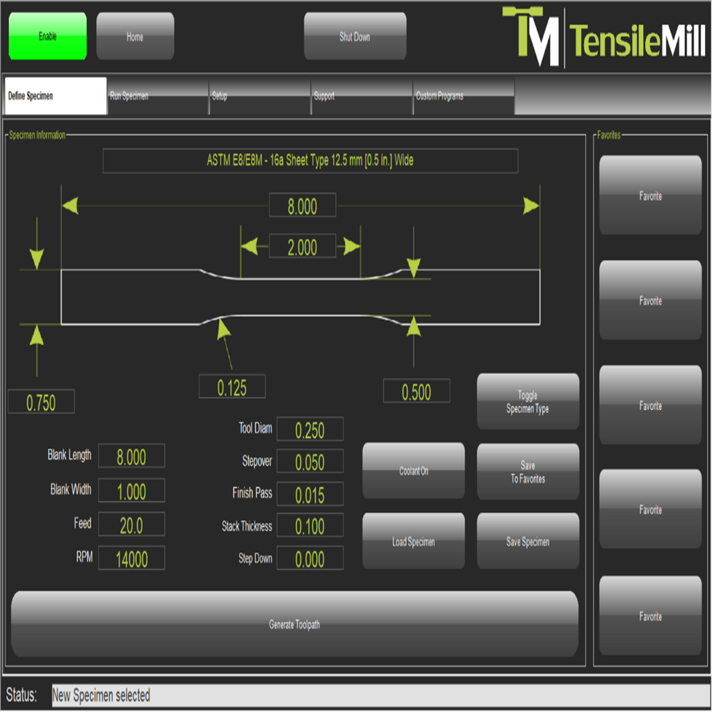
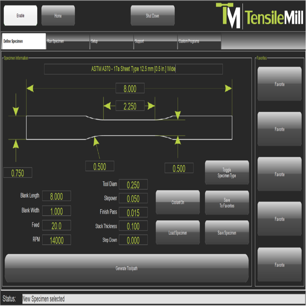
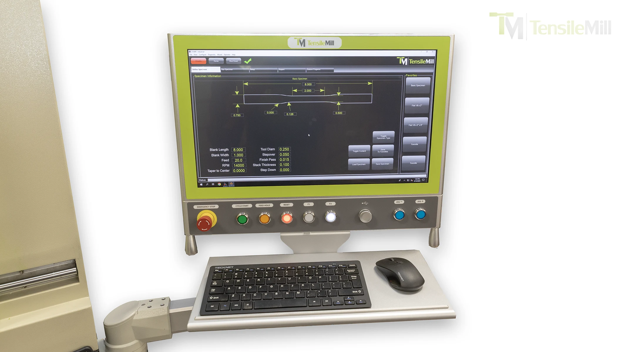
TensileMill CNC MINI is designed so that non-CNC-trained operators can produce standard-compliant flat tensile specimens with just a few guided steps. A large touchscreen runs TensileSoft with pre-programmed tensile geometries and a simple parameter entry workflow.
Ease-of-use highlights:
Guided tensile interface – operators select the standard (e.g., ASTM E8, ASTM A370, ISO 6892), enter key dimensions, and the system generates the toolpath automatically.
Fixture-based workflow – dedicated tensile fixtures ensure repeatable clamping and minimize manual alignment steps.
Clearly labeled steps – loading blanks, starting cycles, and unloading finished coupons follow a predictable pattern, which is quickly learned.
Optional Carbon upgrade gives advanced users full CNC capabilities without complicating the basic tensile workflow.
Training support:
New MINI installations include remote or on-site training, depending on your preference and project scope.
Training typically covers: safe operation, fixture loading, basic parameter entry, tool changing, coolant checks, and common troubleshooting.
Refresher sessions can be arranged when you add new staff or expand your testing program.
If you’d like to review workflow examples or arrange training for your team, visit the
TensileMill CNC MINI product page.
Does the Compact Flat Tensile Test Sample Preparation Machine produce samples that comply with international industry standards?
Yes. The TensileMill CNC MINI is engineered to produce flat tensile specimens that support key international standards such as ASTM E8, ASTM A370, ASTM B557, ISO 6892, and related regional standards (DIN, JIS, etc.), provided the machine is configured with the correct fixtures, tooling, and programmed dimensions.
How the MINI supports standards compliance:
Pre-configured tensile software – TensileSoft includes reference geometries and parameter fields aligned with common standards, reducing the chance of operator entry errors.
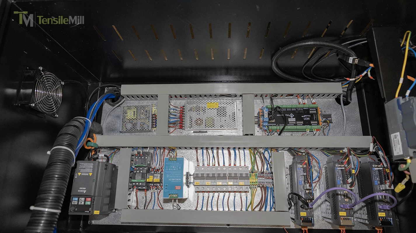
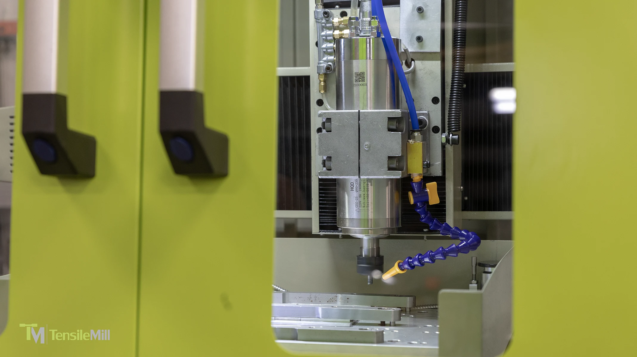
Precision motion system – servo-driven axes on linear rails and a 24,000 rpm spindle support tight tolerances and high-quality edge finishes, which are essential for repeatable mechanical test results.
Standard-specific fixtures – tensile fixtures are designed to hold specimens in a way that preserves gauge length and parallelism during machining.
Important considerations:
Full compliance always depends on correct parameter input, material behavior, and tooling selection; the machine provides the capability, while the operator ensures that the chosen program matches the exact revision of the standard in use.
For audits (e.g., ISO 17025, NADCAP), labs often combine MINI output with independent dimensional verification and documented work instructions.
To confirm compatibility with your specific ASTM/ISO requirements, request a standards review through the
TensileMill CNC MINI page.
How expensive are the maintenance costs for the TensileMill CNC MINI?
Maintenance costs for the TensileMill CNC MINI are generally modest and predictable, especially compared to the long-term cost of outsourcing specimen preparation. The machine is built on a cast iron frame with linear rails, high-speed spindle, and servo drives, all designed for durability in QC environments.
Typical recurring maintenance items:
Coolant – periodic concentration checks and occasional tank cleaning
Tooling – replacement of end mills based on material type and throughput
Lubrication – topping up lubricants for ways and moving components
Preventive maintenance – annual or semi-annual inspections of spindle, drives, and safety systems
Many labs choose to formalize this as a Preventive Maintenance (PM) service plan, which helps:
Extend machine life and protect accuracy
Reduce unplanned downtime and emergency repair costs
Provide documentation that supports internal quality systems and external audits.
Because every lab runs different volumes and materials, actual annual maintenance cost is best estimated alongside your sample throughput and operating hours.
For a preventive maintenance package or a cost-of-ownership estimate tailored to your usage, visit the
TensileMill CNC MINI product page.
How does TensileMill CNC, Inc. mitigate production downtimes for flat tensile sample preparation systems?
TensileMill CNC, Inc. mitigates downtime for flat tensile sample preparation systems (including the MINI and MICRO) through a combination of rapid technical support, strategic spare parts stocking, and structured troubleshooting workflows.
Key elements of downtime mitigation:
Centralized support channel – customers can submit issues through the Request Support portal, phone, or email, providing photos/videos so engineers can quickly diagnose the problem.
Remote diagnostics first – many issues (software settings, parameter errors, minor hardware adjustments) are resolved remotely, often within hours, without waiting for onsite service.
Stocked critical components – common replacement parts (spindles, drives, control electronics, fixtures) are held in stock or available with short lead times to avoid extended machine interruptions.
Preventive maintenance programs – recommended PM schedules reduce the risk of unexpected failures and allow component replacements to be planned during non-critical periods.
For labs where tensile specimen preparation is a bottleneck, this approach means that a machine fault is typically turned into a short interruption, not a multi-week outage.
If you're experiencing an issue or want to review service response options, use the support contact on the
TensileMill CNC MINI page.
What is the average cost range for tensile specimen preparation and testing with the TensileMill CNC MINI?
When you bring specimen preparation in-house with the TensileMill CNC MINI, the effective cost per specimen typically becomes much lower than outsourcing, where market prices often run around $150–$300 per specimen for preparation and testing, depending on complexity and location.
With an in-house MINI, your per-specimen cost is primarily driven by:
Depreciation or lease cost of the machine
Operator time (which often drops significantly once workflows are dialed in)
Tooling and consumables (end mills, coolant, occasional fixture upgrades)
Maintenance (routine PM vs. ad-hoc service)
For example:
A lab running 50–100 flat tensile specimens per month can often reach a break-even point within a relatively short period, after which each additional specimen costs only a fraction of outsourced pricing.
Because every organization has different labor rates, sample volumes, and logistics costs, the best way to estimate your own cost range is to run your numbers through TensileMill’s structured calculator.
To calculate your in-house cost-per-specimen and compare it with outsourcing, use the ROI tools on the
TensileMill CNC MINI page.
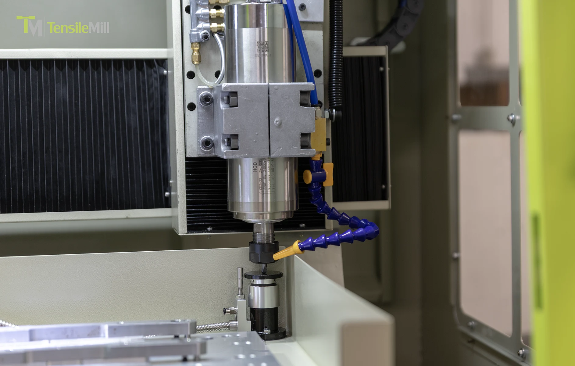
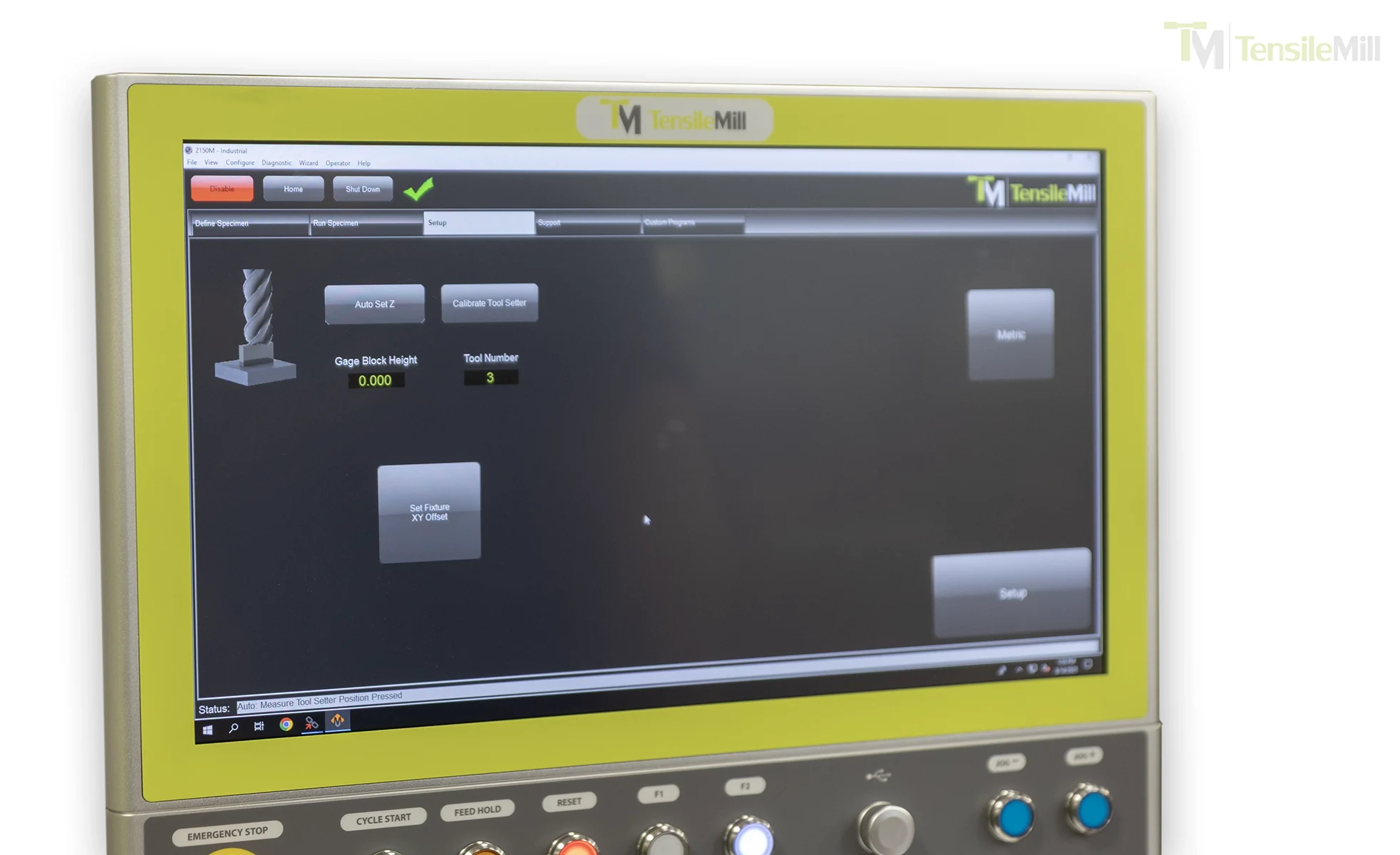
What is the Tool Touch Off Process for the TensileMill CNC MINI?
Earlier MINI models relied on a manual tool touch-off using a reference gauge block, but the latest MINI editions are equipped with an automatic tool setter, allowing operators to touch off tools with a single button press.
With the automatic tool setter, the typical process is:
Load the tool into the spindle and ensure it is clamped to the correct projection.
Move the machine to the tool setting position defined in the control.
Press the tool-set command on the touchscreen.
The machine automatically lowers the tool onto the tool setter, detects contact, and records the exact tool length offset.
The control updates the tool table, and the tool is ready for use in your tensile specimen program.
Benefits of the automatic tool setter:
Faster setup – especially when changing tools between materials or geometries
Reduced risk of human error compared to manual gauge-block methods
Improved consistency of Z-height across multiple operators and shifts
For labs that still prefer or occasionally need manual touch-off (for special tools or unique setups), the traditional gauge-block method remains available in the control, but most day-to-day work is now handled by the automatic tool setter.
To confirm whether your MINI includes the automatic tool setter or to request a demonstration, visit the
TensileMill CNC MINI product page.
What comes with the custom flat tensile sample preparation fixture for the TensileMill CNC MINI?
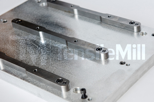
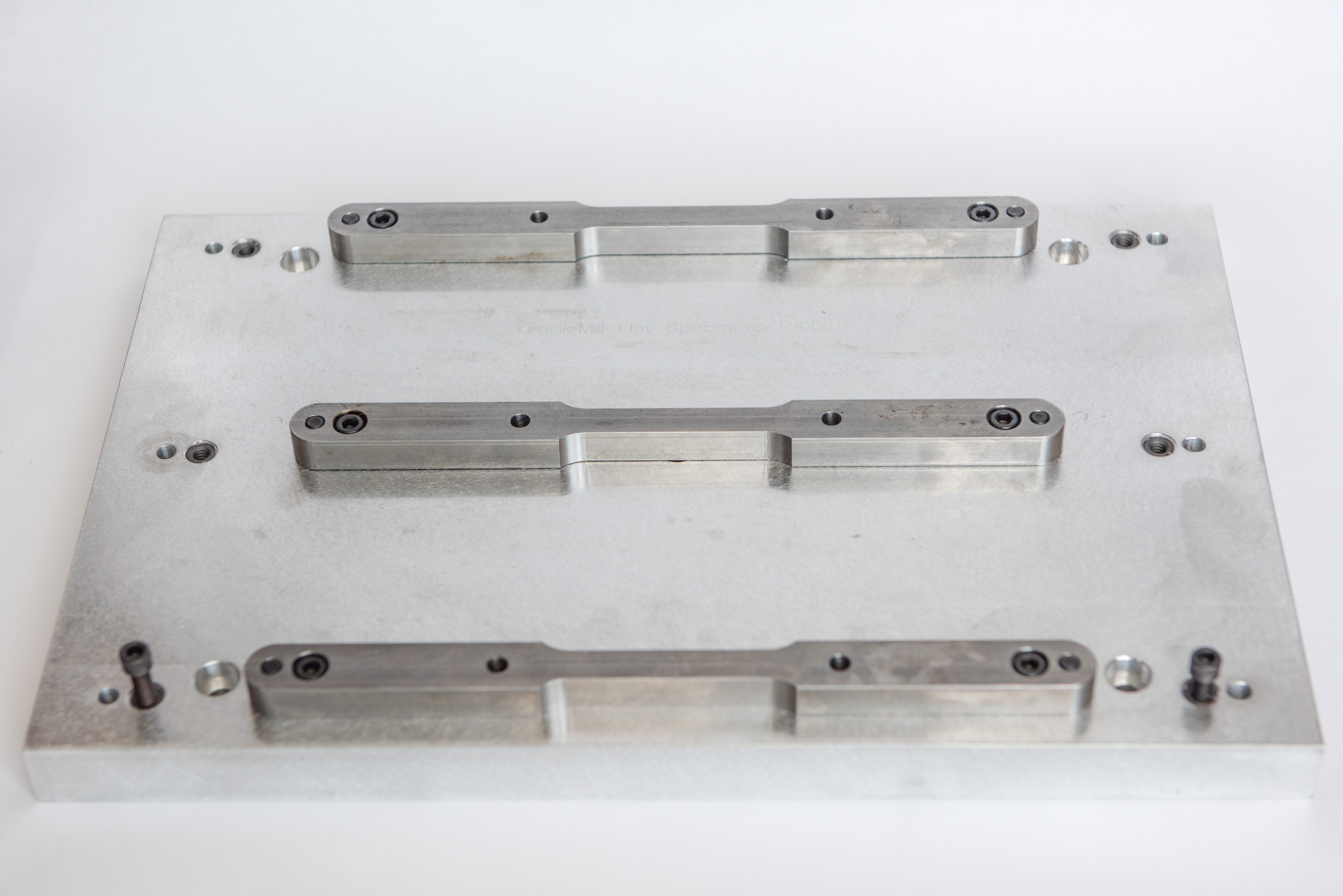
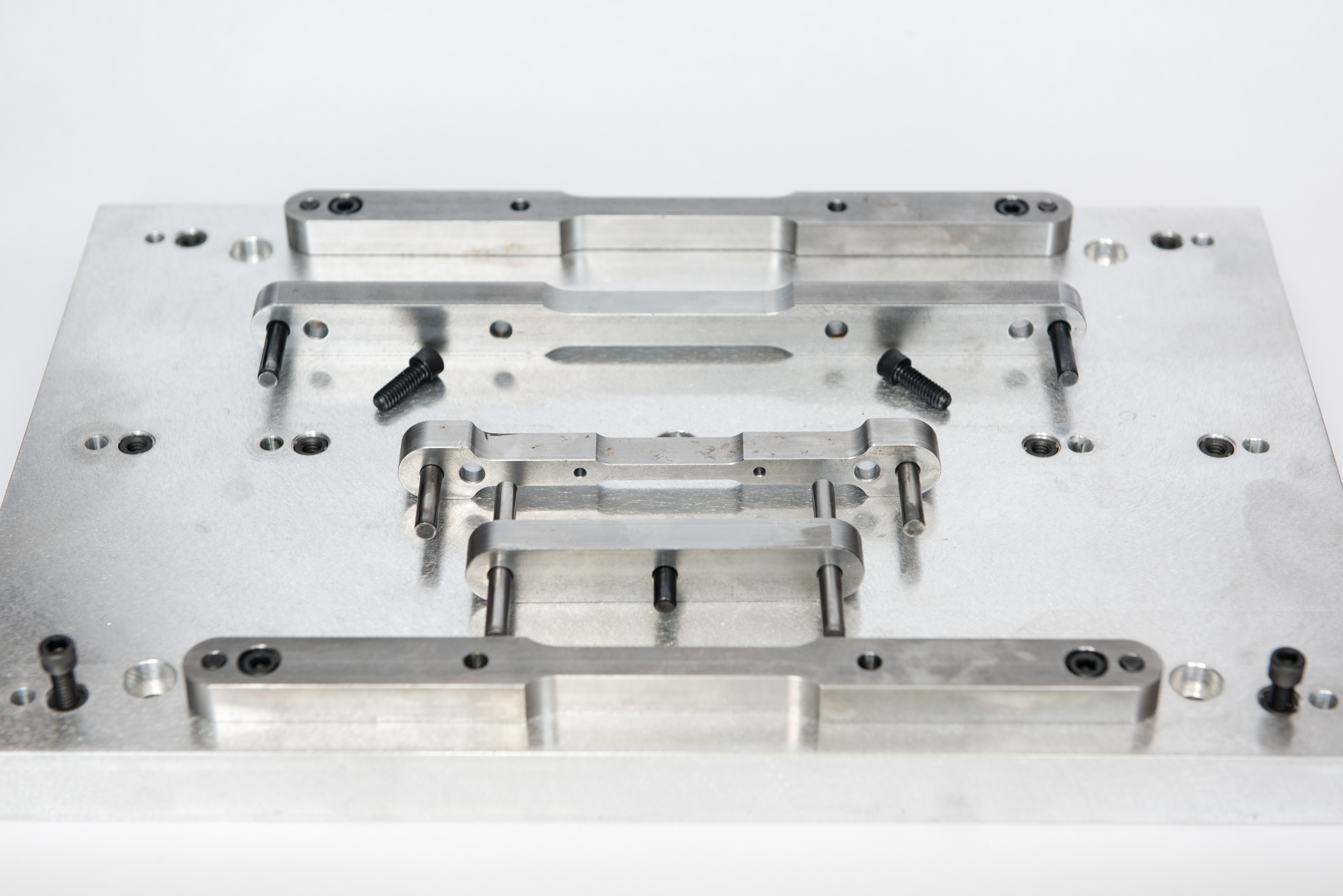
The custom fixture for the TensileMill CNC MINI includes a rigid base with three clamping stations, matched clamp sets in 4 in, 8 in, and 12 in sizes as required, and paired centering blocks, all supplied within the Turnkey Package Advantage at no additional cost.
Each fixture ships with three identical clamps per selected size to populate the three stations. Clamp options cover 4 in (102 mm) subsize, 8 in (203 mm) regular, and 12 in (305 mm) large specimens, selected to suit your material program and gauge length. A standard centering block pair supports the regular and long clamp sets, and a subsize centering block pair aligns the 4 in configuration.
This layout holds multiple blanks at once for consistent alignment and repeatable clamping across batches. Operators can swap clamp sets quickly without re-indicating the workholding, which shortens changeovers and supports higher daily throughput on flat tensile specimens.
During quoting we confirm specimen dimensions and deliver the fixture configured for your parts, ready to run on the MINI.
To review the fixture package, specifications, and ordering options, visit the
TensileMill CNC MINI page.
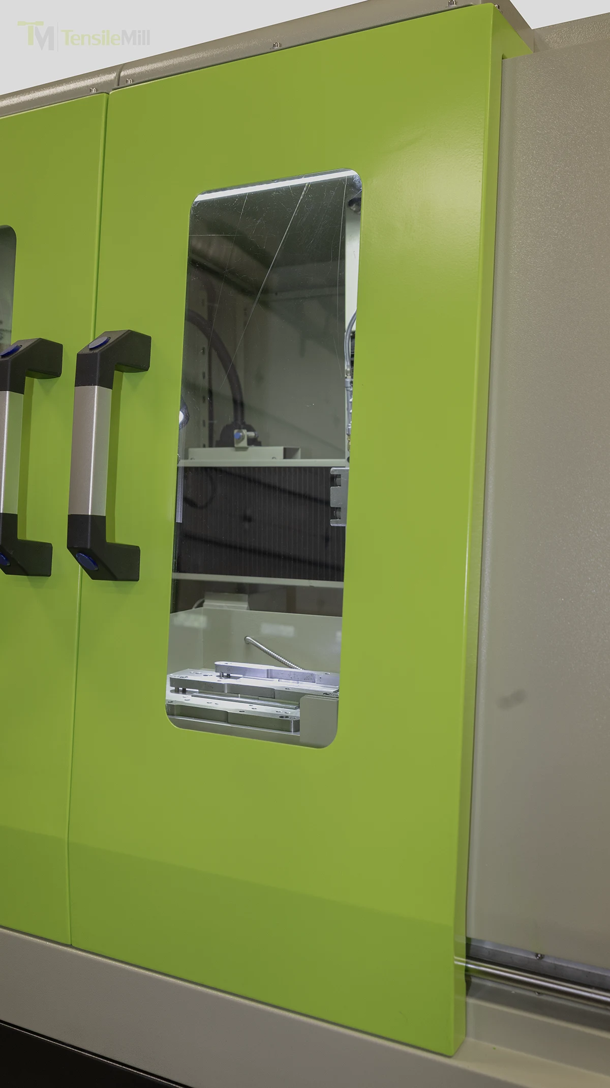
How does the door interlock and safety locking mechanism function on the TensileMill CNC MINI during specimen preparation?
The enclosure uses a door interlock tied to the emergency stop circuit. During a locked machining cycle, if a door is opened, the control triggers an immediate E-stop that halts axis motion, stops the spindle, and pauses the program.
The cycle will not start unless the doors are closed and the interlock is engaged. On recent MINI revisions, a mechanical latch and safety-rated interlock prevent the doors from opening while the spindle is active or while axes are moving, so the enclosure remains closed until the system reaches a safe state. After any E-stop, the operator clears the fault on the control, closes and re-latches the doors, confirms the setup, and restarts from the appropriate step. This design supports safe operation during routine specimen preparation without slowing normal throughput.
If you would like more detail on the interlocked enclosure and control logic, you can review technical information on the
TensileMill CNC MINI page.
What service and technical support do you provide for Flat Tensile Sample Preparation machines?
You receive rapid-response technical support from CNC consultants and application engineers for installation, applications, and day-to-day operation. We respond by phone, email, or live video, with same-business-day acknowledgment for most requests.
Support covers programming and machining for standard-compliant flat specimens, including common geometries used for ASTM E8 metals and ISO 527 plastics when applicable. We help with post-processor setup, G-code verification, cutter and tooling selection, recommended feeds and speeds across aluminum, steel, and polymers, and workholding alignment to maintain parallelism and target gauge length. Remote diagnostics can review controller parameters, tool and work offsets, probing routines, and surface finish outcomes. On request, we provide templated CAM files and sample toolpaths to speed first-article approval and increase throughput.
For ongoing operations, we offer operator training, preventive maintenance schedules, and spare parts assistance for cutters, belts, fixtures, and other wear items. Most consumables ship from North America to keep downtime low. When needed, on-site visits can be scheduled for advanced troubleshooting or calibration checks.
If you would like to plan service and training for your lab, you can review options on the
Flat Tensile Test Sample Preparation Machines page.
How do the door interlock and safety systems operate on the TensileMill CNC MINI?
The TensileMill CNC MINI uses a safety-rated door interlock that ties directly into the machine’s stop circuit. The cycle will not begin with the door open, and the interlock keeps the door latched during cutting to prevent access to the work area.
If the door is opened during an active program, the interlock triggers an immediate emergency stop. Spindle rotation and all axis motion halt, power to the drives is removed, and the control posts a safety fault. After the area is safe, the operator closes the door, acknowledges the fault with the Reset control, and restarts from the program interface. This approach prevents motion while the enclosure is open, reduces the chance of tool or part contact, and supports consistent flat specimen preparation across shift changes. The interlock and emergency stop operate through the hardwired safety loop rather than a software pause, so stopping action is rapid and repeatable.
If you would like more detail about safeguards and operator workflow, you can review technical information on the
TensileMill CNC MINI page.
Will burrs remain on tensile specimens after the cutting cycle on a TensileMill CNC sample preparation system?
Edge condition after machining depends on material type, cutter or insert condition, feed and speed, coolant, and toolpath strategy. With the supplied starter tooling and tuned parameters, burr can typically be minimized to a negligible edge or eliminated. Good practices include matching the cutter or insert grade to the alloy, keeping cutting edges sharp, using adequate coolant, and programming climb milling with a light finishing pass of about 0.005 to 0.010 in (0.13 to 0.25 mm) stock. Adding a small edge break of roughly 0.005 in (0.13 mm) with a chamfer or deburr pass helps reduce handling nicks before testing.
If some burr remains, quick secondary methods are common in tensile labs: hand files, deburring blades, small countersinks, tube deburring tools for round gage sections, fine flap wheels, and nonwoven abrasive pads. Remove only the raised edge so gage width or diameter is not altered, then verify dimensions and surface quality prior to testing. Our team can recommend tooling and parameters for both flat and round workflows to help you hit your required finish with minimal rework.
If you would like to source deburring media, end mills, inserts, and related supplies, you can review options on the
Consumables and Spare Parts page.
What electrical receptacle or outlet is recommended for the TensileMill CNC MINI flat tensile sample preparation machine?
Use a grounded, three-prong, 20 A single-phase receptacle, typically a NEMA 5-20R, for the TensileMill CNC MINI. The machine may be cord-connected to this outlet, or hardwired to a nearby lockable disconnect sized for 20 A.
Most North American labs supply 120 V AC, 60 Hz. A dedicated 20 A branch circuit with hot, neutral, and equipment ground helps prevent nuisance trips during spindle inrush and keeps other instruments isolated from transient loads. Circuit protection should match the 20 A rating, and the outlet should be within safe reach of the machine’s cord to avoid extension cables.
If hardwiring is preferred, a licensed electrician can land the feed at a local disconnect, then to the machine, following local electrical codes and using copper conductors rated for the ambient. Facilities that standardize on different receptacle styles can specify the matching 20 A, three-wire connection during procurement.
If you are planning installation for a new bench space, you can review electrical details and footprint for the
TensileMill CNC MINI.
How do I troubleshoot the coolant pump on my TensileMill CNC MINI?
Coolant pump faults on the TensileMill CNC MINI typically trace to three sources: a jammed impeller or heavy drag from sludge or corrosion after storage; a wiring fault between the breaker and the pump that creates a short and trips protection; or a less common internal motor failure. If the pump starts, moves fluid briefly, then trips the breaker, mechanical binding or restricted flow is the most probable cause.
Lock out and tag the machine. Verify the tank is filled so the pickup and a portion of the belt are submerged, then skim chips and fines. Remove and clean the pump strainer, flush the tank and lines, and check for dried residue. With power disconnected, rotate the impeller by hand; it should turn freely without grinding. If stiff, disassemble the head and clear debris, scale, or corrosion, then reassemble with fresh gasket or sealant as specified. Restore power, confirm correct voltage at the pump leads, inspect connectors for abrasion, and perform a continuity check to ground. If the breaker trips immediately with the pump disconnected, you likely have a branch wiring issue; if it trips only under load, focus on pump mechanics or a failing motor.
For storage or extended idle periods, keep coolant covering the pickup and belt to help prevent corrosion and dry starts, and circulate periodically to minimize settling. If troubleshooting does not resolve the issue, our team can assist with diagnostics or a replacement pump and seals.
If you would like additional details on system layout and service access, you can review technical information on the
TensileMill CNC MINI product page.
How do I determine the optimal spindle speed and feed rate for machining tensile specimens in a specific material?
Optimal speed and feed depend on the material, cutter geometry, coating, and the specimen’s gauge geometry. Start with tooling matched to your alloy or polymer, then validate with a brief trial. TensileMill CNC offers complimentary dog-bone preparation where our engineers cut your samples on flat and round specimen systems such as the TensileMill CNC MICRO or MINI for flat blanks and the TensileTurn CNC series for round bars, typically converging on stable parameters by the second or third cycle. During installation and training, our technicians also tune speeds, feeds, coolant strategy, and toolpaths at your site so production runs are repeatable and surface finish in the gauge section aligns with your testing needs.
A practical workflow is to begin with the cutter manufacturer’s conservative chip load, a shallow axial depth per pass such as 0.050 to 0.100 in (1.27 to 2.54 mm), and moderate radial engagement. Make a short 1 to 2 in (25 to 50 mm) test pass outside the gauge length, then review chip form, temperature at the gauge, spindle load, and finish. Increase feed in small steps until chatter or rising load appears, reduce by about 10 percent, and adjust rpm to stabilize the cut. Use climb milling for flat specimens, sharp inserts on round specimens, and flood coolant or MQL to keep the gauge section smooth, which supports ASTM E8 or ASTM D638 geometry requirements when applicable. Save the final recipe in the controller for repeatable throughput.
If you would like parameter guidance for your material or a complimentary dog-bone trial, you can connect with our team on the
Contact Us page.
Can the TensileMill CNC MINI prepare flat tensile dog-bone specimens directly from sheet metal or other sheet materials?
Yes. The MINI supports two production paths: machining from strips using the included Triple Clamping Fixture, or cutting specimens directly from sheet stock with a dedicated sheet-holding setup. Both workflows are designed to speed up flat tensile coupon throughput while maintaining consistent geometry.
If you prefer strips, cut your blanks to a manageable width and thickness, then stack them in the three-clamp fixture that ships with the machine. Labs commonly cut their starting pieces down to 2 in (50.8 mm) thickness or less. You can load up to 0.5 in (12.7 mm) total thickness per clamp and process the stack in one cycle, which is helpful when batching large runs.
If you prefer sheets, mount the sheet in the supplied sheet clamping arrangement and program the toolpath to remove material from the top side, then finish the external profile. This lets you machine multiple dog-bones from a single sheet in one unattended cycle. The number of parts per run depends on your sheet dimensions and available clamping area. If you have a target sheet size, our team can configure the fixture accordingly so your program nests as many specimens as the sheet allows.
If you would like to compare strip versus sheet workflows in more detail, you can review fixturing options and specifications on the
TensileMill CNC MINI product page.
What tensile specimen geometries and dimensions can TensileSoft prepare?
TensileSoft supports both standard straight-edge and tapered-edge flat tensile specimens. Operators can select common dog-bone geometries from ISO 527 and ASTM D638 or input custom sizes. On compact systems such as the TensileMill CNC MINI, tapered-edge profiles are typically produced up to 0.50 in (12.7 mm) thickness.
In practice, you choose a template or define gauge length, grip width, fillet radius, overall length, and thickness, then clamp the blanks and start the cycle. The software creates the profile and edge transitions, applies optimized toolpaths, and accommodates single-part or stacked cutting to increase throughput. Final size ranges depend on machine travel, fixturing, material, and cutter selection, so your achievable envelope is governed by the specific flat specimen system installed. The same workflow applies across the MICRO, MINI, Classic Upgrade, and XL flat machines, giving plastics and metals labs a fast path to repeatable edges for standard-compliant tensile testing.
If you would like to compare flat-specimen systems and software workflows, you may review details on the
Flat Specimen Preparation Equipment Lineup page.
What are the voltage requirements and tolerances for the TensileMill CNC MINI?
The MINI operates on single-phase 200 to 240 V AC. Do not step the supply down to 110 V, this falls below the internal low-voltage cutoff for several components and the machine will not run.
For reliable startup and machining stability, supply the machine from a dedicated 208 to 240 V branch circuit and connect it directly without intermediate step-down devices. If your facility only has 120 V circuits, coordinate with a qualified electrician to add a 208 to 240 V feed with the appropriate breaker and receptacle. Before commissioning, verify the incoming voltage at the machine under load, label the circuit for the MINI, and keep the power cable run as short as practical to limit voltage drop.
If you would like electrical specifications and installation notes, you can review details on the
TensileMill CNC MINI product page.
Can the TensileMill CNC MINI prepare Charpy impact specimens for ASTM E23 testing?
Yes. With the optional machine vise and appropriate tooling, the MINI can machine Charpy impact specimens in both standard and subsize formats. A skilled operator is recommended because notch geometry and surface finish directly influence impact results.
A typical workflow is to mill the blank to 0.394 in × 0.394 in × 2.165 in (10 mm × 10 mm × 55 mm) for full size specimens, or to the required subsize, then fixture the bar to produce the V-notch. To meet ASTM E23 or ISO 148-1 geometry, target a 0.079 in depth (2.0 mm), a 45 degree included angle, and a 0.010 in notch root radius (0.25 mm). Many labs cut the notch using a dedicated Charpy broach or a form cutter on the MINI, then verify dimensions with a certified notch gauge. For low to moderate volumes, this approach is practical; for higher throughput, the MINI can handle blanking while a separate notching device completes the feature.
Workholding may use a standard vise with soft jaws or a custom fixture that supports multiple bars, and toolpaths typically favor light radial engagement, high spindle speed, and coolant matched to the alloy.
If you would like to review fixturing options and CNC capabilities, you can read more on the
TensileMill CNC MINI product page.
What power, air, and site setup are required to install the TensileMill CNC MINI?
Power connection: 220 V, single phase, 15 A circuit. The machine’s connected load is approximately 3.3 kW. Use a properly grounded outlet following local electrical code.
Fluid systems are self-contained. The recirculating coolant and automatic way lubrication are integrated, so no facility water, drain, or external lube hookups are needed. A compressed-air line is optional and used only if your configuration includes pneumatic accessories.
For placement, this compact floor-standing machine can be located to fit your workspace on a level surface. Many users set a very slight pitch toward the front-right corner to promote quicker coolant return. The machining area is enclosed with an open-top design, which helps contain chips and fines; an overhead hood may be added to align with your facility’s ventilation practices, but it is not required in typical use. Provide reasonable clearance for door movement and routine service access.
If you would like to review connection details and installation considerations, you can read the technical specifications on the
TensileMill CNC MINI product page.
What installation space is required for the TensileMill CNC MINI when preparing flat tensile specimens?
Plan for a machine envelope of 48 in W × 48 in D × 75 in H (1219 mm × 1219 mm × 1905 mm). The operator controller mounts on the left side and needs an additional 12 to 14 in (305 to 356 mm) of lateral clearance for mounting, cable routing, and safe operator access.
Allow rear and overhead clearance per your facility’s safety policies for guarding, ventilation, and service access. Keep the front of the system open for blank loading, workholding swaps, and routine maintenance. If your lab uses chip or dust collection, leave a path for the hose and cabling without creating pinch points. For tight rooms, alcoves, or doorway constraints, our team can provide a placement drawing that reflects your exact layout and access routes.
If you would like to review dimensions and placement guidance for your site, you can explore the specifications on the
TensileMill CNC MINI product page.
What Lubricant Type and Viscosity Does the TensileMill CNC MINI Use?
The MINI ships with an integrated way lubrication system that uses ISO VG 68 way oil. This tacky, anti-wear oil supports smooth motion on sliding ways and linear components. Operators commonly select reputable brands such as Mobil, Shell, or Irving.
ISO VG 68 way oil forms a stable film that reduces stick slip on guideways and helps protect ball screws during continuous specimen milling. Choose a dedicated way lubricant rather than hydraulic, gear, or spindle oils, since way oils contain additives that promote adhesion to vertical and horizontal ways. For reliable performance, keep the reservoir above the sight level, wipe exposed ways before start up, and top off with the same oil grade to avoid mixing chemistries. If your workflow involves frequent material changes or extended runtime, maintaining clean lines and checking metering fittings will support consistent feed accuracy and surface finish on flat tensile blanks.
If you would like additional details on lubrication and machine features, you may review specifications on the
TensileMill CNC MINI product page.
What Coolant System Comes Standard With the TensileMill CNC MINI Flat Specimen Preparation Machine?
The MINI ships with a recirculating, water based coolant system with a 10 gallon tank (37.9 L) and a dedicated pump driven by a 1/8 HP motor (0.093 kW).
Coolant concentration is mixed to match the material being machined, supporting consistent edge finish and tool life for tensile specimen preparation. Compatible fluids include well known metalworking brands such as Cimcool, Hocut, and Blaser. The coolant tank measures 16 in × 24 in × 9.75 in (406 mm × 610 mm × 248 mm), the pump motor runs at 1500 rpm, and the unit accepts 115 V or 230 V input. For most labs, this compact footprint fits beneath or beside the machine, and the recirculating design supports continuous cutting of flat specimens while controlling heat, swarf, and surface quality prior to polishing.
If you are reviewing compact flat specimen systems, you can read coolant and accessory details on the
TensileMill CNC MINI product page.
Can I Watch the TensileMill CNC MINI Prepare a Flat Tensile Specimen?
Video demonstrations are available showing the compact MINI preparing flat tensile specimens from raw blanks. The clips walk through fixturing, selecting a program from the tensile interface, and machining the reduced section on common alloys, including carbon steel and aluminum. You will see tool changes, coolant use, and the resulting geometry suitable for downstream polishing or testing to common standards such as ASTM E8 or ISO 6892 when applicable.
If you prefer a live look, you may arrange an on-site visit at our facility in Maine, USA. Call +1 877 672-2622 to discuss dates, materials you would like us to cut, and any specific grip or fixture considerations for your workflow.
If you would like to preview demos and review technical details, you can explore the
TensileMill CNC MINI page for videos and product information on the equipment page.
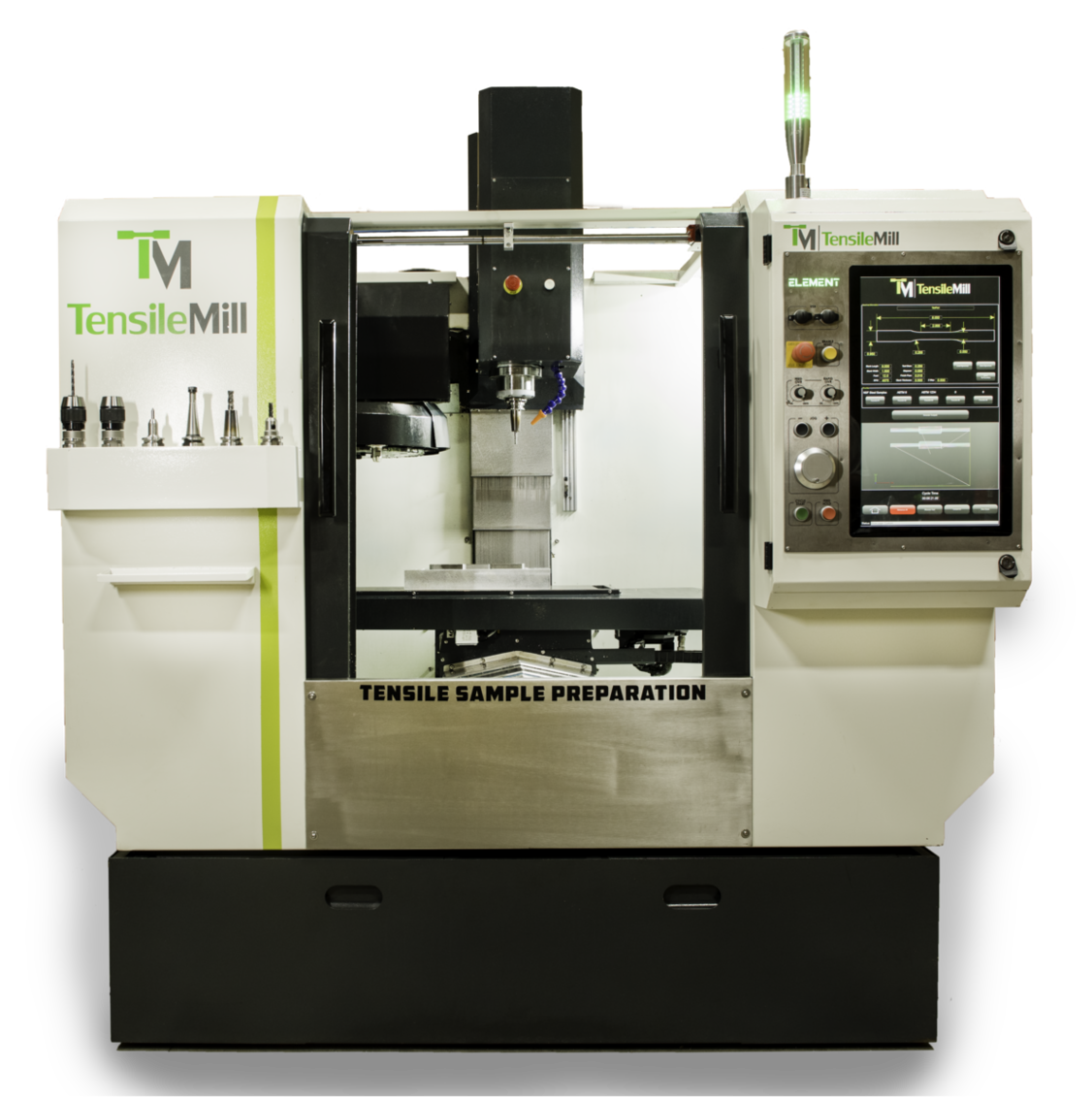
How Do You Set Up and Operate the TensileMill CNC MINI?
Setup and operator onboarding are designed to be quick. You can choose on-site installation and hands-on training, or remote start-up support with factory video modules that walk through uncrating, power-up, the control interface, workholding, and the first test cuts.
For installation, place the machine on a rigid surface, level it, and secure it according to your facility’s safety practices. Connect the specified electrical supply and any required air or coolant, then verify lubrication and splash protection. Load the starter tool library, install the appropriate cutters for your specimen material, and home the axes. Mount the standard vise or fixture plate, then run a dry cycle to confirm travel limits and clearance.
For daily operation, mount your blanks, set work offsets with the probe or edge finder, and confirm clamp positions. Choose a program matched to the material and specimen geometry, such as common shapes defined in ASTM E8, ASTM D638, or ISO 527, then perform a short air cut above the stock. Start the cut, monitor chip evacuation, and record tool wear offsets after the first part. Deburr and, if required, move to polishing to meet gauge-length and surface finish targets. Routine tasks include cleaning chips, inspecting cutters, backing up programs, and completing the operator checklist. If questions come up, the support team can guide you through specific workflows and fixturing choices.
If you would like to review setup steps, sample programs, and training options, you can read more on the
TensileMill CNC MINI product page.
What Standard Clamping Fixture Comes With the TensileMill CNC MINI for Tensile Sample Preparation?
The MINI ships with a Triple Sample Fixture as standard. This clamping assembly holds up to three flat blanks or three stacked sets in one setup, positioning them for parallel machining that produces uniform specimens across all stations.
The workflow is straightforward: the operator loads the blanks, selects the preconfigured program in the control software, and starts the cycle. The machine runs unattended while other tasks are handled, then the operator returns to collect finished tensile specimens. The three-position layout reduces individual handling steps, shortens setup time, and increases throughput without adding complexity. Rigid clamping maintains consistent alignment and surface quality, which supports dimensional repeatability for downstream mechanical testing. The fixture’s layout is practical for daily changeovers and fits common blank sizes used in flat tensile sample preparation, making it a productive default choice for labs and production environments seeking reliable, repeatable output.
If you would like to review throughput features and fixture details, you can learn more on the
TensileMill CNC MINI product page.
What Is Included in the TensileMill CNC MINI Turnkey Package?
The MINI turnkey package includes a base triple-position clamping fixture with one clamp size per station, allowing you to machine at least three flat specimens in a single cycle. The package also includes a material-appropriate ER collet and a matching end mill intended for long term use.
The base fixture accommodates starting blanks up to 12 in (305 mm) in length. If your program calls for different geometries or higher throughput, custom fixturing can be supplied to match your workflow. Additional base fixtures, alternative clamp sizes to match specimen dimensions, and replacement end mills can be ordered at any time to expand capacity or keep spare tooling on hand.
If you would like to compare accessory options or confirm package contents, you can review the details on the
TensileMill CNC MINI product page.
What Upgrade Options Are Available for the TensileMill CNC MINI?
Available upgrades include a production-ready Turnkey Package with an ER collet, a shank end mill, and a custom multi-station fixture tailored to your specimen geometry, so new operators can begin running parts with minimal setup.
For broader CNC capability, the Full Carbon CNC Package adds an advanced control with full G-code programming. This lets the same platform handle auxiliary machining tasks between tensile specimen runs.
Cutting performance can be elevated with a 2.95 hp (2.2 kW) ISO20 spindle upgrade, supporting heavier cuts in thicker blanks and hard alloys while maintaining edge quality. A 3 axis servo motor upgrade increases feed rates and positional accuracy, which helps reduce cycle times and tighten dimensional repeatability on gauge width and shoulder transitions. Together, these options improve throughput, surface finish, and tooling life while giving labs a scalable path as volumes grow.
If you would like to compare package configurations or review specifications, you can explore the options on the
TensileMill CNC MINI product page.
What Recirculating Fluids Does the TensileMill CNC MINI Require?
The MINI uses two recirculating fluids: a closed-loop spindle cooling medium and a water-based cutting coolant in the machine sump. The spindle cooling fluid is typically replaced about once per year. The cutting coolant is topped off as needed and fully changed when a foul odor develops, which many facilities observe after about 6 to 12 months, depending on workload and water quality.
For reliable uptime, check the sump level during routine start-up and replenish with your approved coolant mix. If odor, discoloration, or foaming appears, schedule a drain, clean, and refill. The flood system holds roughly 10 gal (38 L), so keep sufficient coolant on hand for maintenance cycles. For the spindle circuit, replace the fluid annually or sooner if contamination is suspected, then purge air from the loop before returning to production. Following these practices helps maintain surface finish and dimensional stability on flat tensile specimens while reducing unplanned downtime.
If you would like additional maintenance guidance and specifications, you can review details on the
TensileMill CNC MINI product page.
Which Spare Parts Does the TensileMill CNC MINI Use, Where Can I Buy Them, and How Quickly Do They Ship?
For routine upkeep on the MINI flat-specimen machine, the most common consumables are carbide end mills and related tooling. End mills typically range from $30.00 to $85.00 each and can be purchased directly from TensileMill CNC. Over a longer horizon, the main wear component is the spindle. Depending on duty cycle, some production labs replace the spindle at about 6 years, many units operate 10 to 14 years, and in very rigorous, continuous use a replacement may be required after a couple of years. A replacement spindle is about $1,400.00.
Ordering is handled directly through TensileMill CNC. Most consumables and standard spare parts are stocked in-house or ship within a few weeks. Spindles generally carry a short lead time, and expedited options can be discussed for downtime-sensitive situations. If you need help matching tooling to your specimen materials or fixtures, our team can confirm compatibility when you place your request.
If you would like to review compatible tooling and replacement items for this system, you can read more on the
TensileMill CNC MINI product page.
What Consumables Does the TensileMill CNC MINI Use and Where Can I Purchase Them?
Common consumables for the MINI are specialty carbide end mills engineered for flat tensile specimen geometry. We supply application-specific cutters for aluminum and soft alloys, carbon and stainless steels, and nickel-based materials. Share your alloy, hardness, and expected monthly throughput, and our team will recommend the diameter, flute design, and coating to deliver stable edge quality and consistent dimensions.
Typical pricing runs $35.00 to $80.00 per bit, with bundle pricing available for higher usage. You may purchase end mills directly from TensileMill CNC by requesting a quote. Unlike cutters, base and clamping fixtures operate as long-life tooling when maintained, often serving for many years. During installation, your operators receive one day of hands-on training that covers preventative maintenance steps to extend tool life and reduce per-specimen cost.
If you would like model-specific tooling recommendations or to review compatible fixtures, you may read additional details on the
TensileMill CNC MINI product page.
What Are the Benefits of the 3 Axis Servo Motor Upgrade for the TensileMill CNC MINI?
Upgrading to the 3 axis servo motor package provides faster motion and tighter positional control on X, Y, and Z. You get quicker traverses, more precise interpolation, and smoother surface finishes, which directly support advanced CNC milling and repeatable flat specimen preparation on the MINI.
Closed loop feedback and higher torque at low rpm help the machine hold gauge geometry and parallelism more consistently, reduce cutter deflection, and keep chip load stable. Shops cutting difficult alloys or small shoulder transitions see shorter cycle times and fewer touch ups, which can lessen downstream polishing. For labs preparing flat coupons to standards such as ASTM E8 or ISO 6892, the upgrade helps limit dimensional drift across batches, especially on narrow gauges and fillet transitions. The net result is dependable throughput, improved tool life, and consistent parts when sample volume increases.
If you would like to compare motion packages and upgrade options, you can review technical details on the
TensileMill CNC MINI product page.
What Are the Benefits of Upgrading to an ISO 20 Spindle on the MINI?
Upgrading to an ISO 20 spindle on the MINI increases cutting capability and rigidity for flat tensile specimen preparation. The standard spindle is 2 hp (1.5 kW), while the upgrade provides 3 hp (2.2 kW). The added power delivers higher torque at working speeds, supports larger toolholders, and reduces the chance of bogging down in stainless, nickel alloys, and tool steels.
In day-to-day use, you can take deeper stepdowns and higher chip loads while maintaining edge quality and dimensional tolerances, including geometries commonly required for tensile testing under ASTM E8 or ISO 6892. The ISO 20 interface also opens access to a wider range of holders with improved runout control, which helps produce cleaner sidewalls and may cut polishing time. Because the spindle works with lower load for the same material removal, heat and vibration are reduced, which supports longer spindle bearing life and helps the machine stay productive when milling thicker blanks or stacked fixtures.
If you would like to review spindle options and see how they fit your workflow, you can learn more on the
TensileMill CNC MINI product page.
Can I Upgrade the TensileMill MINI to the Full Carbon CNC Software Package?
Yes. The MINI can be quoted with the Full Carbon CNC Package, adding full CNC capability while retaining the dedicated tensile interface for specimen preparation.
With Carbon, the control moves to an industrial platform that includes a 21 in (533 mm) touchscreen, 64 GB storage, and 4 GB RAM, along with WiFi, Ethernet, and USB connectivity. The upgrade unlocks production-grade functions such as standard G-code execution, macro style programming, expanded tool and work offset tables, advanced cutter compensation, helical routines, canned drilling cycles, and scaling or mirroring. Operators can switch between the tensile software and CNC mode on the same controller, so the system prepares flat specimens to ASTM or ISO dimensions and also handles general milling, engraving, or fixture work.
When requesting a quotation, you can ask for the Carbon upgrade to be included so the MINI ships configured for both tensile sample preparation and broader CNC machining tasks that match your lab’s workflow.
If you would like to review upgrade options and specifications, you can explore details on the
TensileMill CNC MINI product page.
What Is the Largest Flat Tensile Specimen the TensileMill CNC MINI Can Prepare?
The maximum specimen size on the MINI is governed by axis travel. The working envelope is 15.75 in × 15.75 in × 7.87 in (400 mm × 400 mm × 200 mm). Within this space, the system machines full-profile flat dog-bones and sub-size coupons that align with common ASTM or ISO dimensions.
Usable blank footprint is slightly reduced by clamp jaws, fixture plates, and tool clearance. For flat coupons, X and Y define the overall outline, while available Z is shared by fixture height, part thickness, and cutter projection. Most profiles from ASTM E8, ASTM A370, and ISO 6892-1 fit well inside the envelope, and plastics such as ASTM D638 typically fall below these limits. For higher throughput, you may nest multiple blanks on a fixture plate as long as the total layout fits within 15.75 in × 15.75 in (400 mm × 400 mm). If you would like an exact fit recommendation, an application review can match your grip tab geometry, thickness range, and fixturing to the travel.
If you would like to review specifications, fixturing options, and example applications, you can read more on the
TensileMill CNC MINI product page.
How Does the TensileMill CNC MINI Compare With the Classic Model for Flat Tensile Specimen Preparation?
The MINI is a compact, lower-cost flat-specimen machining system suited to small and medium workloads, while the Classic configuration targets higher throughput with a larger working area and broader upgrade capacity.
In day-to-day use, the MINI favors labs with limited bench space, frequent material changeovers, and standalone operation. It offers a streamlined footprint, quick setup, and a budget-friendly path to compliant blanks and finished profiles. With optional packages such as advanced workholding, templated CAM, and process monitoring, the MINI scales into a highly economical platform for routine flat specimen preparation. The Classic model accommodates heavier usage, larger fixtures, and expanded automation, making it a strong fit for continuous shifts, wider blank sizes, and multi-operator environments. Both platforms support standard-compliant geometries when paired with the appropriate tooling and fixturing, including common profiles for ASTM E8 or ISO 527. For labs balancing consumable spend and uptime, the MINI optimizes cost per specimen in moderate volumes, whereas the Classic is preferred when sustained duty cycles and accessory flexibility drive productivity.
If you would like a compact flat-specimen solution with scalable options, you can review technical details on the
TensileMill CNC MINI equipment page.
What Is the Current Lead Time for the TensileMill CNC MINI Tensile Sample Preparation Machine?
Lead time for the TensileMill CNC MINI is dynamic and tied to the active build queue. Recent order volume has extended production for some configurations, so availability is confirmed case by case. When you share your configuration and destination, we provide a firm ship date at order placement and identify any expedited build slots that may be open.
Timing varies by package and workflow. Standard MINI configurations typically move through production faster, while custom fixturing, software options, or factory acceptance testing can add build time. Training and installation scheduling, as well as carrier transit, are planned separately from production. If you are working toward a deadline, you may request partial shipments for tooling and consumables, priority scheduling, or a virtual pre-shipment runoff. Your project coordinator tracks the order from confirmation through crating and pickup, keeping you informed at each step.
If you would like real-time availability or to compare configuration options, you can review details on the
TensileMill CNC MINI product page.
What Is the Proper Laboratory Use of the TensileMill CNC MINI for Tensile Specimen Preparation?
The MINI is suited for labs producing about 5 to 45 flat specimens per day where quick setup, repeatability, and small footprint are priorities. It converts metal and composite blanks into tensile coupons through a guided tensile milling interface, allowing operators to pick an ASTM or ISO geometry or enter target dimensions, fixture the blanks, and run consistent cycles with minimal training.
Typical use covers dog-bone specimens for ASTM E8 and ISO 6892-1 metals as well as flat shapes for composite laminates, yielding smooth gauge sections ready for polishing. The rigid platform, dedicated tooling, and saved programs support stable gauge width and radius control across batches while reducing hands-on time between runs. When additional CNC work arises, upgrading to the Carbon Mach4 controller adds full G-code capability for general machining while preserving the tensile templates, so one system handles specimen preparation alongside light CNC tasks.
If you would like to review capabilities, software options, and typical lab workflows, you can explore details on the
TensileMill CNC MINI page.
How Many Flat Tensile Specimens Can I Prepare Per Cycle?
Throughput per cycle depends on the machine configuration, workholding, blank size, and material hardness. Standard flat-specimen setups typically machine one coupon at a time, while optional multi-station and triple-clamp fixtures allow multiple blanks or stacked sets in a single program.
On compact systems, a single-station clamp is common for one-part cycles. Larger or upgraded setups can use multi-station fixtures. With a triple-clamp configuration, operators may load up to three stacked blanks, subject to total stack height, cutter reach, and part rigidity. As a practical reference, many labs run stacks totaling about 1.0 in (25.4 mm), and individual coupons up to 0.5 in (12.7 mm) thick on select models. The achievable part count also varies by alloy and starting thickness, since harder materials and wider gauge sections call for more conservative feeds and additional passes. If you share your material grade, starting thickness, and target geometry, our team can recommend a cycle plan and fixture package that balances part count, surface finish, and tool life.
If you would like to discuss throughput and fixturing for your application, you can connect with our team on the
Contact Us page.
Can I Stack Multiple Blanks for Faster Tensile Sample Preparation?
Yes. Our flat-specimen systems support stacked machining using a dedicated clamping device that accommodates a combined stack height up to 1.0 in (25.4 mm). The clamp grips the full pack so the mill can rough and finish several specimen profiles in one program with stable holding and repeatable alignment.
Stacking is commonly used for metals and polymers to raise throughput while maintaining final geometry. Use uniform blank thickness, register the edges, and verify cutter reach across the full 1.0 in (25.4 mm) height. Apply toolpaths, feeds, and coolant suited to the material to manage heat and burr formation. After machining, separate the coupons, deburr, and measure according to the applicable standard, for example ASTM E8 for metallic flats or ISO 527 for plastics, so each specimen meets the required dimensions and radii. This approach reduces handling time per part without changing compliance, since every coupon is inspected individually.
If your workflow calls for taller packs, unusual geometries, or abrasive alloys, specialty clamps and tooling packages are available to match your specimen design and production rate.
If higher throughput is a priority, you may review model compatibility and fixturing details on the
Flat Tensile Test Sample Preparation Machines page.
What Are the Key Differences Between the TensileMill CNC MINI and XL Machines?
The XL targets higher capacity and automation, while the MINI focuses on compact quality lab workflows. XL machines flat tensile blanks up to 1.0 in (25.4 mm) thick, the MINI handles up to 0.5 in (12.7 mm). XL uses a 5 hp (3.7 kW) spindle and includes an ISO 20 automatic tool changer with 5 tool positions; the MINI has a 2 hp (2.2 kW) spindle with a single tool, with an optional ATC upgrade. XL construction combines cast iron with a fabricated steel frame for added rigidity, while the MINI uses a cast iron structure.
Select the XL when you need multi step milling programs, reduced cycle time from automated tool changes, and consistent performance on thicker materials. It favors production floors and larger labs where throughput, durability, and multi tool routines such as roughing, finishing, and edge breaking are common. The MINI fits smaller QC labs and engineering groups preparing standard flat specimens in moderate volumes, where benchtop footprint, straightforward operation, and lower power draw are priorities. Both platforms produce accurate flat specimens, so the choice comes down to thickness range, program complexity, and available space.
If you would like to review dimensional specs and automation options, you can explore details on the
TensileMill CNC XL page.
What Are the Key Differences Between the TensileMill CNC MINI and XL Tensile Sample Preparation Machines?
Both platforms prepare flat tensile specimens, yet they target different workloads and lab environments. The XL accepts starting blanks up to 1.0 in (25.4 mm) thick, while the MINI is suited for blanks up to 0.5 in (12.7 mm). The XL is a larger, industrial machine for high throughput and oversized material, whereas the MINI’s compact footprint fits smaller quality labs and limited floor space.
Power and tooling also differ. The XL uses a 5 hp (3.7 kW) spindle that supports heavier cuts and faster cycle times. The MINI is equipped with a 2 hp (1.5 kW) spindle that is ideal for small batches and moderate materials. For automation, the XL ships with an ISO 20 automatic tool changer with 5 tool positions, enabling roughing, finishing, and edge breaking in one program. The MINI comes with a single-tool spindle and can be upgraded to an automatic tool changer if your workflow grows.
For longevity and stability, the XL combines a cast iron base with fabricated steel elements, while the MINI uses a robust cast iron construction. In practice, the XL favors multi-shift production and unattended operation, and the MINI favors quick setups, lower power cuts, and tight spaces.
If you would like to compare footprint, power, and automation details in depth, you can review specifications on the
TensileMill CNC XL Large Flat Tensile Test Sample Preparation Machine product page.
What Additional Maintenance Steps Extend the Life of a Tensile Sample Preparation Machine?
Routine preventive maintenance and a clean workspace go a long way. Keep the lubrication reservoir topped with the recommended oil, wipe down exposed surfaces, and remove chips after each shift to reduce wear on moving components and guarding.
For daily care, vacuum chips instead of blowing them into seals, clear the chip tray, and dry any coolant residue on the table, vises, and fixtures. Confirm that the automatic lubrication system is cycling and that lines are intact. Inspect the spindle taper and tool holders for debris, then lightly clean and re-seat them to protect runout. Keep the coolant or mist system clean by using approved fluids and replacing filters as needed. Periodically check way covers, door interlocks, cable carriers, and the condition of belts, fasteners, and guarding. Verify that the air supply is clean and dry to protect valves and actuators. Back up machine parameters and software, and record service actions in a simple log so you can spot trends. Train operators to run a brief warmup program at start of day, handle specimens and tooling carefully, and report any unusual noise, heat, or vibration immediately.
If you would like maintenance guidance tailored to your setup or a recommended service interval, you can connect with our team on the
Contact Us page.
How Many Tensile Specimens Can Be Prepared Per Cycle?
Throughput per cycle varies by material, specimen geometry, and workholding. On flat CNC tensile systems, you can machine a single coupon in one setup or run a batch using multi-station clamps, fixture plates with nesting, or stacked blanks when thickness and rigidity allow.
The achievable count depends on thickness and hardness, which influence cutter engagement, pass strategy, and allowable stack height. Standards such as ASTM E8 or ISO 6892 define gauge length and width, which dictate part spacing and fixture pocket layout. Tough alloys and thicker stock increase cycle time and often favor one-up machining with separate rough and finish passes, while thinner sheet and softer metals suit nested batches that deliver higher parts per hour. Tool diameter, corner radii, coolant delivery, and changeover method also affect real-world yield. If you share your alloy, initial blank size, thickness, and target standard, our team can provide an application-specific parts-per-cycle and hourly throughput estimate.
If you would like to compare batch fixturing and table sizes, you can review models and options on the
Flat Tensile Test Sample Preparation Machines page to learn more about throughput planning.
What Types of Base Fixtures Are Available for Tensile Sample Preparation Machines?
Flat tensile preparation systems from TensileMill CNC are supplied with a stainless steel base fixture tailored to the specimen geometry in your method library. Optional clamping fixtures expand the holding envelope for different blank lengths, covering approximately 15 in down to 4 in (381 mm to 102 mm). Each package also includes an ER collet and carbide end mills, with only the cutters considered routine consumables.
The base fixture is built for long service life and resists wear in high-throughput labs. It is configured to support common flat specimen profiles used in standards such as ASTM E8 for metals, ISO 6892-1, and ASTM D638 for plastics when applicable to your workflow. When your starting blank length changes, selecting the matching clamping fixture maintains full contact and stable clamping, which helps hold gauge-width tolerance and finish quality during milling. End mill life ranges from weeks to months based on part volume, material hardness, and blank thickness, so keeping a small stock of our coated carbide tools helps prevent unplanned downtime.
If you would like to compare fixture options or check current availability, you can review details on the
Tensile Sample Preparation Consumables, Fixtures, and Spare Parts page.
What Is the Typical Lifespan of End Mills for TensileMill CNC Milling Machines?
Tool life varies because it depends on material hardness, blank thickness, toolpath strategy, coolant use, and spindle setup. Our systems ship with specialty carbide end mills in bright finish or Alcrona Pro coating that are engineered for tensile specimen machining. In production labs, these cutters commonly deliver extended service across multiple batches, including high-throughput programs, but there is no single hours-or-parts figure that applies to every application.
For the longest life, match the geometry and coating to the workpiece: bright finish for aluminum and other nonferrous materials, AlCrN-type coatings such as Alcrona Pro for steels, stainless, and nickel alloys. Use conservative radial engagement, climb milling on profiles, ample coolant, and rigid fixturing. Keep spindle runout at or below 0.001 in (0.025 mm). Replace a cutter when surface finish begins to dull, burrs increase, spindle load trends upward, or edge wear and micro-chipping become visible under magnification. Keeping a spare set of identical tools on hand helps maintain consistent specimen quality and uptime.
If you would like application-specific tooling guidance or to review stocked options, you may explore the
Consumables and Spare Parts page for end mills matched to our sample preparation machines.
How Do Flat Tensile Specimen Machines Keep the Gauge Section Centered During Two-Sided Machining?
Symmetry is achieved with a one-setup flip process that keeps the blank registered to the same clamping faces for both passes. The machine completes the first side, pauses, and the operator rotates the fixture while the work offset and datums remain unchanged. The second operation runs a mirrored toolpath around the same centerline, so the gauge section stays centered and thickness remains uniform.
Dedicated reference surfaces in the fixture control X and Y location, while the clamping stack maintains Z datum, preventing drift that commonly appears when parts are reindicated on manual equipment. Matching step-downs, cutter paths, and feed strategies for both sides keep cutting forces balanced, which helps avoid taper, bow, or offset shoulders. The same workflow applies to multi-part fixtures or stacked blanks, so every coupon in the set carries the same geometry. For labs preparing flat specimens to ASTM E8 or ISO 6892, this approach supports gauge section alignment and parallelism requirements without extra setup time.
If you would like to compare fixturing and workflow options, you can review model details on the
Flat Specimen Preparation Equipment Lineup page.
What Does the Flip-Jig Fixture Do in Two-Sided Tensile Specimen Machining?
The flip-jig is a dedicated workholding fixture that clamps the specimen blank for two-sided milling, keeps the centerline aligned, and preserves the work offset during rotation. By holding the blank in a consistent datum, it allows the part to be rotated when prompted by the software without changing the machining origin.
In practice, you clamp the raw blank, machine the first side, then rotate the part 180 degrees within the same fixture when the program prompts a flip. Because the datum remains constant, the controller continues from the same zero, which reduces thickness mismatch, shoulder radius offset, and gauge-section runout compared with manually re-centering on a general-purpose CNC. The result is tighter correlation between faces, faster changeovers, and stable parallelism across batches.
One flip-jig is supplied with the system and is selected to match expected specimen length. Available sizes include 4 in (101.6 mm), 8 in (203.2 mm), and 12 in (304.8 mm). Selecting the correct size matches the clamping span to the blank, improving stability and surface finish on thin or long samples.
If you would like to compare compatible systems and fixturing options, you can review details on the
Flat Tensile Test Sample Preparation Machines page.
How Many Steps Are Required to Prepare One Flat Tensile Specimen on a TensileMill CNC?
Most users complete one flat tensile specimen in five steps. Select the standard or custom profile on the touchscreen, clamp the blank in the flip fixture against the alignment stop, start the first-side program, rotate the flip fixture when prompted without re-centering, then resume the cycle to machine the second side.
The built-in library covers common profiles such as ASTM E8 or ISO 527, so dimensions are loaded once and stored for repeat runs. Toolpaths, spindle speed, and motion control are automated, which keeps operator involvement to alignment and the single flip. The fixture datum preserves registration between sides, producing consistent gage width and surface finish for reliable tensile results across batches.
If you would like to compare model options for flat specimen machining, you can review capabilities on the
Flat Specimen Preparation Equipment Lineup page.
How Is the Flood Coolant System Maintained and Refilled?
Our flat-specimen machining systems use a recirculating flood coolant housed in the machine base, so all plumbing, filtration, and return flow stay inside the enclosure. Routine care focuses on fluid level, concentration, and chip control to keep cut quality and pump life stable in a lab setting.
To refill, open the sump access inside the enclosure and add premixed water-soluble coolant until the sight gauge or fill mark is reached. Typical lab units hold about 10 gal (37.9 L). After filling, run the pump briefly to verify steady return flow to the tank. For day-to-day operation, top off with the same premix rather than straight water to avoid diluting the blend.
Maintenance includes checking concentration with a refractometer and adjusting with concentrate or water per the coolant manufacturer’s chart, cleaning the intake screen and return tray so chips do not starve the pump, and skimming tramp oil as needed. Plan full tank cleanouts on a usage-based interval, for example every few months, which includes draining, wiping sediment, flushing lines, and replacing disposable filters if fitted. No external coolant supply is required, which keeps service simple for laboratories and small production cells.
If you would like a model-by-model look at coolant features for our flat specimen mills, you can review details on the
Flat Tensile Test Sample Preparation Machines page.
Is In-House Tensile Specimen Preparation More Cost-Effective Than Outsourcing?
For labs with steady testing, in-house preparation typically reduces total cost after the initial equipment purchase, because the marginal cost per specimen becomes far lower than paying per batch externally. For occasional or sporadic testing, outsourcing can be practical since there is no upfront capital spend.
Outsourcing carries variable charges that repeat with every order: setup and machining fees, packaging, two-way shipping, potential rush charges, and idle time while parts are in transit. Those costs scale directly with demand and can rise with tighter tolerances or special profiles for standards such as ASTM E8 or ISO 527. If rework is needed, the cycle repeats.
In-house shifts spending to a fixed asset plus predictable items like cutters, inserts, coolant, and routine maintenance, along with operator time. Once a flat or round specimen system is installed, the next sample mainly reflects tool wear and minutes of machine time, and adjustments happen immediately without courier delays. Facilities running regular production checks, R&D iterations, or academic coursework usually see per-specimen cost drop as throughput increases, especially when using batch cycles or multi-part fixtures to machine multiple blanks in one run.
If you would like to discuss throughput, staffing, and payback for your lab, you can connect with our team on the
Contact Us page.
How Do I Choose Between Flat and Round Tensile Specimen Preparation Systems?
Start with your material form and the target geometry required by your test method. Flat preparation is ideal for sheet, plate, or molded panels, commonly used for ASTM E8 metals or ISO 527 plastics. Typical flat dog-bone sizes include 0.25 to 1.00 in (6 to 25 mm) gauge width with 1.00 to 2.00 in (25 to 50 mm) gauge length and 0.125 in (3.2 mm) fillet radii. Round preparation suits bar, rod, wire, or cast buttons, with frequent sizes of 0.250 to 0.500 in (6 to 13 mm) diameter and 2.00 to 4.00 in (50 to 100 mm) gauge length. Target tolerances often hold ±0.001 in (±0.025 mm) in the gauge section and 0.001 in TIR (0.025 mm) concentricity for round specimens.
Consider throughput and handling. For high coupon volumes across multiple alloys, a fixtured flat CNC system supports repeatable nesting and quick changeovers. For rounds, a programmable lathe-style machine with tailstock support and center drilling maintains straightness on longer pieces, for example 6 to 12 in (152 to 305 mm) overall length, while flood or mist coolant protects both metals and polymers.
Confirm UTM and grip compatibility early. Flats pair well with wedge or pneumatic grips using 1 to 2 in (25 to 50 mm) jaw widths. Rounds may require collets, shoulders, or threaded ends such as 0.500-20 UNF, with shoulder perpendicularity within 0.002 in (0.05 mm). Surface finish affects results, so polish the gauge section longitudinally to Ra ≤ 32 µin (0.8 µm), or to 16 µin (0.4 µm) for notch-sensitive materials, and verify dimensions against the selected standard during first-article inspection.
If you are comparing flat and round preparation solutions, you can explore the
TensileMill CNC Homepage to review product families on the page.
How Do I Choose Between Flat and Round Tensile Specimen Preparation Systems?
Selection depends on your product form, the governing standard, and downstream gripping. For sheet, plate, and extrusions, a milling-based system produces flat coupons to ASTM E8/E8M or ISO 6892-1 for metals, and ASTM D638 or ISO 527 for polymers. For bar, rod, and forged stock, a lathe-style system machines round specimens, typically 0.500 in (12.5 mm) nominal diameter with 2.00 in (50 mm) gauge length for ASTM E8, or subsize options when thickness limits the section.
Consider precision and finish. Flat machining supports tight edge tolerance around ±0.001 in (±0.025 mm) and surface finish near 32 µin Ra (0.8 µm) when tooling is sharp. Turning round specimens makes concentricity and straightness easier to control, often within 0.001 in (0.025 mm) TIR, which reduces bending errors. If your lab needs a mirror finish for strain extensometers, plan on a polishing pass to achieve 16 µin Ra (0.4 µm) or better.
Throughput and fixturing also matter. Flat systems can fixture multiple blanks per cycle, which is efficient for sheet from 0.020 to 0.250 in (0.5 to 6.0 mm) thickness. Round systems suit continuous runs from 0.125 to 1.000 in (3.2 to 25.4 mm) diameter bar. Verify your UTM grip style, wedge grips for flat widths like 0.500 in (12.5 mm) or collet or threaded holders for round shoulders, and confirm overall length, for example 6.0 to 10.0 in (152 to 254 mm), matches the machine and standard.
For additional guidance, you can connect with our team on the
Contact Us page.
How Do I Choose the Right Flat Tensile Sample Preparation Machine for ASTM E8, ASTM D638, or ISO 527 Work?
Start with your material range and blank size. If most coupons come from sheet, a compact work envelope such as 12 in × 12 in (305 mm × 305 mm) is efficient. For plate cutting or multiple-up nesting, consider larger travels, for example 24 in × 36 in (610 mm × 914 mm). Match spindle power and tooling to your thickness, such as 0.020 in to 1.50 in (0.5 mm to 38 mm), and plan for tool diameters from 0.0625 in to 0.375 in (1.6 mm to 9.5 mm).
If you would like to compare sizes, options, and workflows side by side, you can review model details on the
Flat Tensile Test Sample Preparation Machines page.
How Do I Choose the Right Flat Tensile Specimen Preparation System for My Throughput and Materials?
Start by quantifying volume and changeover frequency. If one profile takes about 3 minutes of cut time plus 1 minute of handling, stacking 3 blanks per cycle yields roughly 45 specimens per hour. Look for rigid fixturing that supports stacked thickness targets, for example 0.50 in (12.7 mm) total, and verify chip evacuation so buried layers do not overheat or burr.
Match cutting strategy to material. Typical starting surface speeds are 600–1000 SFM (183–305 m/min) for aluminum, 150–300 SFM (45.7–91.4 m/min) for carbon steel, 100–200 SFM (30.5–61.0 m/min) for stainless, and 80–120 SFM (24.4–36.6 m/min) for hardened alloys with TiAlN-coated carbide. Use 0.0015–0.004 in (0.038–0.102 mm) per-tooth feed and shallow stepdowns of 0.02–0.06 in (0.50–1.50 mm) to control heat and edge quality on the gauge section.
Select software that locks in specimen geometry from a standards library and exports a run record. For metals reference ASTM E8 or ISO 6892-1, and for plastics reference ASTM D638 or ISO 527. Aim for a uniform gauge finish of 63 µin Ra (1.6 µm) or better, and plan a light final pass of about 0.005 in (0.13 mm) to remove tool marks and minimize burrs. For thin sheet, a vacuum table with a sacrificial backup of 0.25 in (6.35 mm) improves flatness and edge integrity.
For labs with frequent size changes, an automatic tool changer and quick-swap jaws reduce cycle losses, while larger work envelopes support multi-up fixtures that increase hourly output without adding operators.
If you want a side-by-side look at compact and full-size options, you can review model details on the
Flat Specimen Preparation Equipment Lineup page.
How Do I Select the Right Flat Tensile Specimen Preparation Machine for Metals, Composites, and Polymers?
Start by matching expected material range and blank size to the work envelope and clamping options. For typical flat coupons, ensure the machine accommodates blank thickness from 0.02 to 0.50 in (0.5 to 12.7 mm) with rigid parallel clamping. If you process hard alloys, confirm cutter stability and spindle torque suitable for up to 60 HRC, plus coolant delivery and effective chip evacuation for stainless and nickel grades. For composites and polymers, prioritize dust extraction and heat control.
Define accuracy targets based on your lab’s method. Many teams aim for gauge width tolerance of ±0.002 in (±0.05 mm), shoulder radius within ±0.005 in (±0.13 mm), and edge burr less than 0.002 in (0.05 mm) to reduce notch effects. When preparing metals to ASTM E8 or ISO 6892, or plastics to ASTM D638 or ISO 527, verify that the software can call standard geometries, edit dimensions, and lock feeds to prevent operator deviation.
Evaluate throughput and automation that actually save minutes per coupon. Look for a probing routine to locate blanks, a tool changer with finishing and roughing tools, and fixtures that allow stacking within the travel area, for example 8 in × 12 in (203 mm × 305 mm). A practical workflow includes a rough pass, a finish pass at reduced step-over, and a light deburr or polish to reach an Ra near 63 µin (1.6 µm) for metals, while using lower surface speeds on polymers to avoid heat-affected edges.
If you would like to compare sizes, controls, and automation options, you can review detailed options on the
Flat Specimen Preparation Equipment Lineup page.
What Dimensional Tolerances And Surface Finish Are Recommended For Flat Tensile Specimens Prepared By CNC Milling?
For metallic coupons prepared to ASTM E8/E8M or ISO 6892-1 geometry, most laboratories target reduced-section width and gauge length within ±0.002 in (±0.05 mm), overall length within ±0.010 in (±0.25 mm), and gauge flatness within 0.002 in (0.05 mm). Aim for a surface finish of 32–63 µin Ra (0.8–1.6 µm) on the gauge section to support stable extensometer contact and consistent strain. Break all edges lightly, about 0.005–0.010 in (0.13–0.25 mm), and remove burrs without narrowing the net width. Shoulder radii should follow the selected standard; where custom, hold radius mismatch under 0.002 in (0.05 mm).
Use stable fixturing on a rigid sacrificial backer, then rough and finish. A typical finishing pass removes 0.010–0.020 in (0.25–0.50 mm) per side with climb milling to minimize recast and burr formation. Keep the work below 150 °F (65 °C) with flood coolant or MQL so temper or residual stresses are not altered. Fresh carbide end mills around 0.250 in (6.35 mm) handle shoulders efficiently, with smaller tools near 0.125 in (3.18 mm) for tight radii.
Verify width at three locations in the gauge using a micrometer with 0.0005 in (0.01 mm) resolution, confirm straightness and parallelism with a granite square or indicator, and document actual dimensions on the traveler before polishing. For plastics per ASTM D638 or polymers to ISO 527, use the same approach, but prioritize lower heat input and gentler edge breaks to avoid notch sensitivity.
If you would like to compare capacities, controls, and footprints, you can review model details on the
Flat Specimen Preparation Equipment Lineup page.
How Do I Choose The Right Flat Tensile Specimen Preparation Machine For ASTM E8 Or ISO 527 Workloads?
Start by matching your material mix and blank thickness to the equipment class. For sheet and thin plate in the 0.020–0.060 in (0.5–1.5 mm) range, a compact system with vacuum workholding and a built-in template library efficiently mills subsize coupons with 2.0 in (50 mm) or 1.0 in (25 mm) gauge lengths. For thicker sections up to 1.00 in (25 mm), a rigid floor machine with higher torque and an automatic tool changer maintains stable cycle times and tool life.
Confirm the machine can hold the tolerances your method requires. Flat tensile coupons for metals and polymers commonly target width and thickness within ±0.002 in (±0.05 mm), straightness within 0.004 in per 6 in (0.10 mm per 150 mm), and a smooth gauge section that avoids notch initiation. A finish of 63 µin Ra (1.6 µm Ra) or better in the gauge length is a practical benchmark. Preloaded libraries for ASTM E8, ISO 527, or ASTM D638 reduce programming risk while still allowing custom geometries.
Evaluate fixturing and process controls. Vacuum or magnetic fixtures excel for thin stock under 0.080 in (2.0 mm); mechanical vises or step clamps suit thicker blanks up to 1.00 in (25 mm). Use appropriate coolant to manage heat and burrs in stainless or nickel alloys, and sequence roughing, semi-finish, then finish passes so final dimensions settle before the contour cut.
If you would like to compare models and review specifications, you can explore options on the
Flat Specimen Preparation Equipment Lineup page.
Which Milling Parameters Produce ASTM E8-Compliant Edges on Flat Specimens Using the MINI?
Edge condition directly affects tensile results, and both ASTM E8 and ISO 6892 call for smooth, nick-free edges with correct radii. On the MINI, use rigid fixturing, sharp carbide end mills, and consistent flood coolant concentration, typically 6 to 10 percent. A practical baseline for a 0.25 in (6 mm) tool is to rough with moderate radial engagement and then finish with a light, stable cut to control heat and burrs.
Starting points by material, expressed as surface speed and chip load: aluminum 600 to 1,000 SFM (183 to 305 m/min), 0.0015 to 0.003 in/tooth (0.038 to 0.076 mm/tooth); carbon steel 250 to 350 SFM (76 to 107 m/min), 0.0010 to 0.0020 in/tooth (0.025 to 0.051 mm/tooth); 300-series stainless 120 to 180 SFM (37 to 55 m/min), 0.0008 to 0.0015 in/tooth (0.020 to 0.038 mm/tooth); nickel alloys 30 to 60 SFM (9 to 18 m/min), 0.0005 to 0.0010 in/tooth (0.013 to 0.025 mm/tooth). For roughing, use 20 to 35 percent radial engagement with stepdowns of 0.050 to 0.100 in (1.3 to 2.5 mm) in aluminum, 0.020 to 0.050 in (0.5 to 1.3 mm) in steels, and 0.010 to 0.020 in (0.25 to 0.5 mm) in nickel alloys.
Leave 0.010 in (0.25 mm) stock per side, then finish at full depth with 5 to 10 percent radial engagement and a reduced feed for a clean, uniform edge. Deburr lightly with a fine abrasive pad or 320-grit paper, verify gauge width and fillet radii, and document the setup to keep results repeatable across lots.
If you would like additional parameter examples and fixturing options, you can review technical details on the
TensileMill CNC MINI equipment page.
What Work Envelope, Power, And Accuracy Does A Compact Flat Tensile Specimen Machine Provide For ASTM E8 And ISO 6892?
The system provides a working travel of 15.75 x 15.75 x 7.87 in (400 x 400 x 200 mm), suitable for most ASTM E8, ASTM B557, and ISO 6892 flat geometries. The standard triple clamping fixture holds three blanks up to 1.5 in (38 mm) wide per station to support repeatable nesting. Starting with near-net-thickness stock reduces cut time, heat, and burr formation.
A 3 hp (2.2 kW) water cooled spindle reaches 24,000 rpm. Programmed feed capability is up to 500 ipm (12.7 m/min). The tool interface uses ER20, with an ISO20 option, and accepts shanks to 0.47 in (12 mm). A common workflow roughs the profile with a 0.250 in (6.35 mm) end mill, then applies a light finish pass to meet gauge section edges and straightness expectations in the cited standards.
Position repeatability is about 0.01 mm. The enclosure is approximately 72 x 43 x 44 in (1829 x 1092 x 1118 mm) with doors closed, and about 72 x 73 x 52 in (1829 x 1855 x 1321 mm) open. Recommended floor area is 82.7 x 78.5 in (2100 x 2000 mm). Machine weight is roughly 1500 lb (680 kg) for rigidity. Electrical input is 220 V single phase at about 15 A. Typical sound at the operator position is 70 to 90 dB, so plan hearing protection and chip evacuation for harder alloys.
For dimensional drawings, fixturing options, and software details, you can review the
TensileMill CNC MINI product page.
What Workspace, Fixturing, and Utility Requirements Does This Compact Flat-Tensile Specimen Machine Need?
The machining envelope provides 15.75 in × 15.75 in × 7.87 in (400 mm × 400 mm × 200 mm), which comfortably covers common flat specimen geometries used in ASTM E8, ASTM B557, ASTM A370, and ISO 6892 programs. Operators can run blanks cut from strip or sheet, then finish profiles and radii with the integrated tensile software for consistent gage width and shoulder transitions.
The base fixture includes three clamping stations, enabling three work stacks per cycle for higher throughput. With the stacking accessory, each station can secure up to 1.00 in (25.4 mm) of combined specimen thickness. Clamp sets are configured to your program and typically include 4 in, 8 in, and 12 in lengths (102 mm, 203 mm, and 305 mm), supporting subsize through long-gage dog-bones. This setup maintains parallelism and repeatability while minimizing repositioning time.
Electrical and utilities are straightforward for lab environments. The machine operates on 220 V, 15 A, with a 3-prong 20 A receptacle or hardwired to a disconnect, and it accepts 200–240 V input. Coolant is a recirculating 10 gal system (38 L) typically supplied as a water-based formulation matched to your materials. An optional pneumatic line may be used where applicable. For operator safety, an interlock prevents door opening during cutting, and any attempt to open the enclosure triggers an immediate E-stop to halt motion.
If you would like deeper technical details, you can review specifications and options on the
TensileMill CNC MINI product page.
How Can a Compact CNC Machine Flat Tensile Coupons to ASTM E8 or ISO 6892 With Burr-Free Edges?
Start with rigid workholding. For sheet and plate, use a vacuum fixture or low-profile clamps with a clean sacrificial backer. On thin stock under 0.125 in (3.2 mm), support the blank with a flat, rigid layer to prevent chatter. Program the prescribed fillet radii per the drawing in ASTM E8 or ISO 6892, and leave 0.010 in (0.25 mm) of stock on the profile for a finishing pass.
Choose sharp carbide tools. A 0.250 in (6 mm) 3-flute for general profiling and a 0.125 in (3 mm) tool for tight radii work well. For aluminum, rough at 8,000 to 18,000 rpm with 40 to 80 ipm (1.0 to 2.0 m/min) feed and 0.020 in to 0.060 in (0.5 mm to 1.5 mm) axial depth. For carbon steels, use 3,000 to 6,000 rpm with 10 to 20 ipm (0.25 to 0.50 m/min) and similar or lighter depths. Use climb milling, stable coolant or mist, and a final 0.005 in (0.13 mm) finish pass at higher rpm to minimize burrs and tool marks.
After machining, lightly break edges with a nonwoven wheel or 400 to 600 grit paper, avoiding nicks in the reduced section. Target a surface roughness of 32 to 63 µin Ra (0.8 to 1.6 µm) on the gauge length. Verify critical dimensions to ±0.002 in (±0.05 mm) or tighter per your quality plan. If polymer coupons are required to ASTM D638, reduce surface speed and feed, use polished cutters, and maintain the same finishing strategy for clean, notch-free edges.
If you would like application details and dimensional guidance, you can review technical information on the
TensileMill CNC MINI product page.
What Workholding And Tooling Practices Maximize Throughput On A Compact Flat Tensile Specimen Machine?
Use a multi-station fixture and stack blanks where permitted. For typical metallic coupons, stacking up to 1.0 in (25.4 mm) total thickness per clamp increases cycle efficiency while maintaining rigidity. Ensure blank edges sit flush, then verify parallelism within 0.002 in (0.05 mm) across the stack to avoid taper. Apply consistent clamping across stations and probe or touch off at the same reference before each batch to keep gage length and shoulder alignment stable.
Select sharp carbide end mills sized to your smallest internal radius. A 0.375 in (9.5 mm) 2–3 flute works well for aluminum at 0.0015–0.003 in/tooth (0.038–0.076 mm/tooth). For carbon and alloy steels, use 3–4 flute tools at 0.0008–0.0015 in/tooth (0.020–0.038 mm/tooth) with flood coolant at 6–10 percent concentration. Rough with 0.040–0.080 in (1.0–2.0 mm) axial stepdowns, then leave 0.010–0.015 in (0.25–0.38 mm) stock for a full-depth finish pass at 5–10 percent radial stepover to produce clean shoulders and fillets.
Match the standard-specified fillet radius and keep edges smooth and free of nicks, as required by ASTM E8 and ISO 6892 to minimize stress risers. After machining, perform a light hand deburr that does not alter dimensions, then verify width, thickness, and radius with calibrated gauges. The TensileMill CNC MINI’s compact platform supports these practices while maintaining consistent, repeatable results in daily lab workflows.
If you would like to review specifications and workflow options, you can explore details on the
TensileMill CNC MINI product page.
How Should Labs Choose Between Flat-Specimen and Round-Specimen CNC Equipment For ASTM E8 and ISO 6892 Programs?
Start with your incoming material and governing standard. Sheet, strip, and plate typically drive a milling-type system for dog-bone coupons, while bar, rod, and machined components favor a lathe-style system for round bars. If the specification calls for a proportional round sample or threaded ends, a round-specimen machine is the efficient path. When standards permit either form, choose the geometry that best represents the product form and simplifies measurement for your team.
Match machine capability to tolerances and finish targets. A good benchmark for flat coupons is ±0.002 in (±0.05 mm) on width and thickness with smooth fillet transitions. For round bars, plan for diameter control within ±0.0015 in (±0.04 mm) and concentricity near 0.001 in (0.025 mm). Many labs target Ra 32–63 µin (0.8–1.6 µm) in the gauge, achieved with sharp tooling, proper coolant, and light finishing passes. Common dimensions include 2.00 in (50 mm) gauge length for flat sub-size coupons and 0.505 in (12.83 mm) diameter round specimens where allowed by ASTM E8/E8M.
Consider throughput and features. If you produce many round bars, a rigid lathe with tailstock support, threading cycles, and optional bar feed improves cadence. For varied flat work, look for travels around 12 in × 6 in × 6 in (305 mm × 152 mm × 152 mm), fast workholding, and an automatic tool changer. Labs that routinely test both sheets and bars often deploy one of each style to keep schedules predictable and results consistent.
If you would like to review configuration options for both flat and round systems, feel free to connect with our team on the
Contact Us page.
How Should Labs Choose Between Flat-Specimen CNC Mills and Round-Specimen CNC Lathes?
Start with incoming stock and the governing standard. Sheet, strip, and plate are most efficiently machined as flat dog-bones on a milling platform, while rods and bars are best prepared as round specimens on a lathe. For metals, ASTM E8/E8M and ISO 6892 outline proportional geometries, so select the machine that matches the required coupon form. If thickness is limited, flat coupons are often the practical path. When both are allowed, round bars can simplify stress calculations and reduction-of-area measurements.
Build your quality targets into the program and inspection plan. Common lab goals are diameter within ±0.001 in (±0.025 mm) for round gauges, width and thickness within ±0.0015 in (±0.04 mm) for flat gauges, and fillet radii within ±0.002 in (±0.05 mm). Aim for 32 to 63 µin Ra (0.8 to 1.6 µm) on the gauge section. Leave finish stock of 0.030 to 0.060 in (0.8 to 1.5 mm) for final passes, use sharp tooling, and apply coolant to avoid altering the surface layer. Deburr lightly, then polish only as needed to remove tool marks without changing dimensions.
Match the machine to throughput and workflow. A benchtop mill can produce a flat coupon in a few minutes, while a lathe with a tailstock and proper centers keeps TIR under 0.002 in (0.05 mm) across the gauge. For mixed workloads, many labs pair a flat system from the TensileMill CNC line with a round-prep TensileTurn unit to cover all materials efficiently.
If you would like to discuss selection criteria for your materials and standards, feel free to connect with our team on the
Request a Quote page.
How Should I Set Up CNC Tooling, Fixturing, And Tolerances For Flat Versus Round Tensile Specimen Preparation?
For flat coupons, use a rigid vise or dedicated plate fixture that supports the gauge and fillet regions, and verify parallelism of the work surface within 0.001 in (0.025 mm). Keep clamp pressure low near the gauge to avoid distortion. For round bars, hold in a precision collet or soft-jaw chuck with a live tailstock center, and keep total indicated runout at or below 0.001 in (0.025 mm). Add 60° center holes with an entrance diameter near 0.10 in (2.5 mm) to maintain concentric support, and limit unsupported overhang to 3–4 in (75–100 mm).
Tooling differs by geometry. Flat specimens respond well to carbide end mills, 3/8–1/2 in (10–12 mm) diameter, with a light finishing pass of about 0.010 in (0.25 mm) per side using climb milling. Deburr edges minimally, about 0.005 in (0.13 mm). For round specimens, use finishing inserts with 0.016–0.032 in (0.4–0.8 mm) nose radius, depth of cut 0.004–0.008 in (0.10–0.20 mm), and feed 0.003–0.006 in/rev (0.08–0.15 mm/rev). Face ends square and add a 0.010 in × 45° (0.25 mm × 45°) chamfer. In both cases, apply flood coolant at 5–10 percent concentration to control temperature.
As practical targets, hold width or diameter within ±0.002 in (±0.05 mm), straightness within 0.002 in per 6 in (0.05 mm per 150 mm), and surface finish in the gauge section between 32–63 μin Ra (0.8–1.6 μm). Verify geometry against the selected standard, such as ASTM E8/E8M or ISO 6892 for metals and ASTM D638 or ISO 527 for plastics. Measure round diameters at three axial locations, and for flat coupons measure width and thickness in the necked region. Avoid cold work by keeping the part under 120°F (50°C), then, if needed, apply a light longitudinal polish to remove tool marks.
If you would like to review equipment options and sizing for your lab, you can connect with our team on the
Contact Us page.
What Tolerance, Concentricity, and Surface Finish Targets Should We Use for Flat vs Round Tensile Specimens?
For flat coupons prepared to ASTM E8/E8M or ISO 6892, labs commonly hold width and thickness within ±0.002 in (±0.05 mm) and keep fillet radii within ±0.005 in (±0.13 mm). Cut edges should be smooth, typically 63–125 µin Ra (1.6–3.2 µm), with machined faces, if required, at about 32–63 µin Ra (0.8–1.6 µm). Break sharp edges lightly, about 0.005–0.015 in (0.13–0.38 mm), and ensure the gauge section is uniform through thickness. Verify at multiple points across the reduced section, not just at mid-length.
For round bars, diameter control drives data quality. A practical target is ±0.001 to ±0.002 in (±0.025 to ±0.05 mm) on the gauge, total indicated runout at or below 0.001 in (0.025 mm), and straightness within about 0.002 in over 6 in (0.05 mm over 150 mm). Surface finish on the gauge is typically 32–63 µin Ra (0.8–1.6 µm). If threaded grips are specified by the standard, cut threads after finishing the gauge to avoid distortion, and use 60° center holes to support the work during turning.
Process tips help you achieve these targets. On flat systems, use full-face fixturing, finish with a light climb-mill pass around 0.005 in (0.13 mm) radial, apply coolant, then deburr without rounding the gauge. On round systems, use a collet or soft jaws with a live center, finish in multiple light passes of 0.002–0.004 in (0.05–0.10 mm), and polish longitudinally. Preloaded templates in TensileMill CNC and TensileTurn CNC equipment help enforce geometry and compliance checks.
If you would like to discuss your testing requirements, feel free to connect with our team on the
Contact page.
How Do I Choose Between Flat and Round Tensile Specimen CNC Systems for ASTM E8 and ISO 6892 Work?
Start with material form and the governing standard. Sheet, strip, and plate, typically 0.04–0.50 in (1.0–12.7 mm) thick, are prepared on a flat-specimen CNC mill per ASTM E8/E8M or ISO 527. Bars and rods, often 0.25–1.00 in (6.4–25.4 mm) diameter, are turned on a round-specimen CNC lathe for ASTM E8 or ISO 6892 work. When a material could be tested either way, follow the product form specified by the standard to keep results comparable.
For flat coupons, hold width and thickness uniformly, probe stock before cutting to minimize taper to under 0.0008 in (0.02 mm), and program the correct shoulder radii from the selected method. Use sharp carbide end mills, climb milling, and flood coolant to avoid cold work. Many labs target edge quality that deburrs to a smooth finish near 32–63 µin Ra (0.8–1.6 µm).
For round bars, center-drill each end, support with a live center, and limit total indicated runout to 0.001 in (0.025 mm) across the gauge length. A 0.015 in (0.40 mm) insert nose radius and light finishing passes help achieve a uniform surface and stable diameter. If your workload regularly includes both sheets and bars, the most efficient path is one dedicated machine of each type. If you must pick one first, select the platform that covers at least 80 percent of your daily specimens.
If you would like to compare round-specimen options, you can explore details on the
All Round Sample Preparation Products product page.
What Tolerances And Surface Finish Should Flat Tensile Specimens Meet Before UTM Testing?
For metallic dog-bone coupons per ASTM E8/E8M or ISO 6892-1, hold gauge width and thickness within about ±0.001 to ±0.002 in (±0.025 to ±0.05 mm). Keep shoulder transitions smooth to the specified radius, and target a gauge-section roughness of 32 micro-in Ra or better (0.8 µm). For plastics under ASTM D638 or ISO 527, dimensional limits are typically wider, yet edge quality and uniform thickness across the gauge length, often 2 in (50 mm), remain critical.
On a flat CNC mill, leave 0.020 to 0.040 in (0.5 to 1.0 mm) stock for finishing. Use a sharp 2 or 3-flute carbide tool, climb-mill the final contour with a light step-over near 0.010 in (0.25 mm), and apply ample coolant to cap heat. Deburr mechanically, then polish along the loading axis through progressively finer abrasives until the target Ra is reached. Remove any longitudinal tool marks that could seed cracks.
Verify thickness and width with calibrated micrometers, confirm gauge length with a template, check shoulder radii with radius gauges, and measure Ra on the gauge section with a profilometer. Mark IDs outside the gauge, clean off coolant residues, and condition specimens to the temperature and humidity required by the selected standard.
If you want to review machine options for flat-specimen preparation, you can explore details on the
Flat Tensile Test Sample Preparation Machines equipment page.
How Do You Prepare Forged Tensile Specimens For ASTM E8 Testing?
Start by selecting the sampling direction specified on the drawing, usually parallel to the primary grain flow of the forging. Remove surface scale and decarburized layers before laying out the blank. For common ASTM E8 subsize flats, target a 2.00 in (50 mm) gage length with about 0.50 in (12.5 mm) gage width, or apply the 4D rule for round bars. Keep the reduced section centered and coplanar with the forging’s working direction to avoid mixed microstructures.
Machine the profile on a dedicated specimen preparation system. Use flood coolant and conservative finishing parameters to avoid work hardening, for example 0.010 in (0.25 mm) radial depth of cut with 0.002–0.006 in/rev (0.05–0.15 mm/rev) feed on steels. Finish the gage length longitudinally and aim for Ra ≤ 32 µin (0.8 µm). Break edges lightly, about 0.010 in (0.25 mm), to prevent nicks that can trigger early fracture.
Before testing, mark two punch or scribe marks 2.00 in (50 mm) apart, verify straightness within roughly 0.002 in per 6 in (0.03 mm per 150 mm), and confirm grip sections match the selected ASTM E8 specimen type. During mounting, align the shoulders in the grips and tighten evenly to minimize bending from off-axis loading.
If you want repeatable, standards-based coupon machining with built-in specimen libraries, you can review
Flat Tensile Test Sample Preparation Machines on the product page.
Which Pre-Test Checks Catch Hidden Preparation Errors In Flat Tensile Specimens?
Start with geometry. Measure gauge width and thickness at multiple points with micrometers, then verify fillet radii with radius gauges or an optical comparator against ASTM E8/E8M or ISO 6892-1 drawings. Mark and confirm the gauge length, commonly 2.0 in (50 mm), and record the exact values on the traveler for traceability.
Review surface and edges. Target a gauge-section roughness at or below 80 µin Ra (2.0 µm). Under 10× magnification, look for burrs, EDM recast, waterjet striations, laser HAZ tint, or grinder chatter. Reject parts with nicks at the radius or gauge margins; light, uniform deburring is acceptable if it does not change profile.
Do a quick alignment and handling check before mounting. Clean gauge faces with acetone or isopropyl alcohol, then load a dummy to verify even grip contact. If bending strain is monitored per ASTM E1012, keep it within accepted limits such as below 5%. Until testing, store specimens at 68–73 °F (20–23 °C) and below 50% RH to reduce oxidation and residue transfer.
If you would like a closer look at system capabilities, you can explore details on the
TensileMill CNC – Flat Specimen Preparation product page.
How Should Surface Finish and Edge Quality Be Controlled for Reliable ASTM E8 and ISO 6892 Tensile Results?
Target a gauge-section roughness of 80 µin Ra (2 µm) or finer for most metals. For high-strength or brittle alloys, work toward 32–63 µin Ra (0.8–1.6 µm). Create a dedicated finish pass of about 0.005 in (0.13 mm) with climb milling and coolant, then clean the gauge section with acetone. Extensometer contact pads should be flat within about 0.001 in (0.025 mm) over the contact length.
Protect the profile. Break sharp edges lightly, about 0.005–0.010 in (0.13–0.25 mm), avoiding a large chamfer that reduces area. Inspect the entire perimeter at 10× to catch nicks and micro-notches. If blanks are cut by waterjet or EDM, leave 0.020–0.040 in (0.5–1.0 mm) stock and remove striations or recast with a final mill or grind. After laser cutting, remove the heat-affected layer by grinding 0.004–0.008 in (0.10–0.20 mm) from the gauge walls.
Record finish, edge break, and inspection magnification with each lot. Verify final dimensions per ASTM E8 or ISO 6892 drawings, and keep grip faces clean to prevent slip that masks surface-related problems.
If you want controlled Ra and scratch direction without changing geometry, you can explore details on the
Automatic Longitudinal Polisher System equipment page.
Which CNC Features Help Produce ASTM E8 or ISO 6892-Compliant Flat Tensile Specimens?
For metals qualified to ASTM E8 or ISO 6892, select a CNC mill with standards-ready templates and precise axis control. Program gauge width and fillet radii per the selected specimen type, then hold gauge width within ±0.002 in (±0.05 mm) and radii within ±0.010 in (±0.25 mm). A rigid table, low spindle runout under 0.0004 in (0.01 mm), and consistent clamping keep the gauge section centered and repeatable from part to part.
Use climb milling with a light finish pass around 0.005 in (0.13 mm) to clean edges. Target a smooth edge and surface roughness near Ra 32 to 63 µin (0.8 to 1.6 µm). Apply flood or mist coolant and keep part temperature below 140 F (60 C) to avoid unwanted thermal effects. Deburr with a small 0.005 to 0.010 in (0.13 to 0.25 mm) edge break and confirm smooth fillet blending into the gauge.
In-process probing helps verify blank alignment, compensate tool wear, and confirm gauge width before release. For ISO/IEC 17025 workflows, log tool IDs, offsets, and CMM checks of width, thickness, and radius, then archive programs and inspection data for audits. If cutting thicker plate, confirm torque at low rpm and fixture reach for blanks up to 12 in × 24 in (305 mm × 610 mm).
If you want to compare platform sizes and control packages, you can explore details on the
Flat Tensile Test Sample Preparation Machines equipment page.
How Do I Choose a CNC Tensile Specimen Preparation Machine for ASTM E8 or ISO 6892 Work?
Start with sample types, materials, and volume. For typical ASTM E8 flat coupons near 0.25 in thick (6.35 mm), target rigid fixturing, travel around 12 in × 12 in (305 mm × 305 mm), and a 3 hp spindle (2.2 kW). Repeatability near ±0.0005 in (±0.013 mm) helps keep gauge width and fillet transitions inside tolerance. For batch work, use a vise or vacuum fixture that holds 6 to 12 blanks.
Program tooling around standards radii. A common subsize radius is 0.5 in (12.5 mm). Rough with a 3/8 in (9.5 mm) end mill, leave 0.005 in (0.13 mm), then finish using climb cuts to clean edges. On 0.25 in thick (6.35 mm) steel, feeds of 15 to 30 in/min (380 to 760 mm/min) with mist or flood cooling limit burrs and heat. Use ASTM E8 or ISO 6892 templates to shorten setup.
Before releasing parts, check gauge width, thickness, and radii with calibrated tools and record values. Ask for ISO/IEC 17025 traceable alignment assistance aligned with ASTM E1012, and verify your UTM per ASTM E4 or ISO 7500-1. Add quick weekly checks with a 6 in (152 mm) ground bar and keep offset notes so the next operator starts from a known reference.
For model comparisons and specifications, you can review options on the
Flat Specimen Preparation Equipment Lineup equipment page.
Which CNC Machining Parameters Matter Most For ASTM E8 And ISO 6892 Flat Tensile Specimens?
Specimen geometry drives data quality before the UTM ever loads the part. For a common ASTM E8/E8M flat specimen, hold width to 0.500 in ±0.010 in (12.5 mm ±0.25 mm), use a 0.50 in (12.5 mm) fillet radius, and keep gauge length at 2.00 in (50 mm). ISO 6892 workflows often use 1.97 in or 3.15 in (50 mm or 80 mm) gauge lengths. Any burr, scratch, or asymmetry near the shoulders shifts stress away from the gauge and can trigger invalid fracture outside the test section.
During CNC milling, use a cutter that matches the programmed radius, then leave a small stock for a contour finishing pass to stabilize edge quality. Aim for surface roughness near 63 µin Ra (1.6 µm) or better and keep burr height under 0.002 in (0.05 mm). Maintain shoulder symmetry within a few thousandths, for example ±0.002 in (±0.05 mm), to limit bending.
Practical checks include a quick CMM or template verification of width and radius, a 10× visual edge inspection, and a light deburr that does not roll material into the gauge. Thermal control with coolant helps maintain size when cutting long blanks.
If you would like to review machine options and specifications for flat specimens, you can explore details on the
Flat Tensile Test Sample Preparation Machines equipment page.
How Do I Qualify a CNC Milling Workflow for ASTM E8 and ISO 6892 Specimens?
Start with the target drawing. Program the CNC and cut a pilot lot of 10 flats from typical stock. Measure width, thickness, gauge length, and fillet radius with calibrated tools. Record surface roughness and aim for Ra ≤ 63 µin (1.6 µm). Fix the cutting recipe, for example a 0.250 in (6.35 mm) end mill, 8,000 rpm, 20 ipm (508 mm/min), climb milling on the finish pass with coolant.
Control the setup. Set vise or fixture torque to 15 ft-lb (20 N·m). Check edge condition on a bench microscope and verify radii with gauges, for example 0.50 in (12.7 mm) if that matches the drawing. Target dimensional repeatability of ±0.001 in (0.025 mm). Establish a wear limit, then replace the tool after 300 in (7.6 m) of cut path or when Ra drifts above 63 µin (1.6 µm). Run a gage R&R on width and thickness with 3 operators.
Connect machining to the test system. Verify force per ASTM E4 and alignment per ASTM E1012. Confirm the extensometer at 2.00 in (50.0 mm) under ASTM E83 or ISO 9513. Keep a traveler linking each specimen ID to CNC program revision, tool lot, and measurements. Re-do the study if blank thickness changes by over 0.040 in (1.0 mm) or the end mill diameter shifts by 0.010 in (0.25 mm).
If you would like to review flat-specimen machining options, you can explore details on the
Flat Tensile Test Sample Preparation Machines product page.
How Should I Specify a CNC Machine for Flat Tensile Specimen Preparation?
Start with the standards you run and the specimen geometry. The machine should hold gauge length and fillet radii for ASTM E8 and ISO 6892 templates, for example 2 in (50 mm) gauge length with radius accuracy within ±0.005 in (±0.13 mm). Look for controlled toolpaths that create burr free edges and consistent width and thickness, with a typical edge break near 0.010 in (0.25 mm) and surface finish around 32 to 63 µin Ra (0.8 to 1.6 µm).
Match capacity to your blanks. Verify travel and Z clearance against your largest coupons, for example a table that accepts 12 in × 24 in (305 mm × 610 mm) stock and about 4 in (100 mm) vertical space. Rigid workholding that clamps the sheet along the neutral axis reduces chatter and taper. A spindle that can hold steady feed at low chip loads, roughly 10 to 60 ipm (0.25 to 1.5 m/min) for thin alloys, with flood or mist cooling, helps protect edge quality.
Check workflow items. Touchscreen programs with preloaded specimen families cut setup time and limit operator variability. Ask for alignment and calibration support to ISO/IEC 17025, plus ASTM E4 force verification and ASTM E1012 frame alignment, so the machine and the test results track together. For high volume, options such as automatic clamping, tool length probing, and multi part nesting can shorten cycle time without sacrificing dimensional control.
If you want to compare capacities and controls side by side, you can review model details on the
Flat Tensile Test Sample Preparation Machines equipment page.
How Does the TensileMill CNC MINI Speed ASTM E8 Flat Specimen Preparation?
Operators load blanks, zero the stock, and select an ASTM E8 template in TensileSoft. The software preloads gauge length options, shoulder radii, and grip widths, then posts toolpaths without manual G-code. For stacked blanks, use parallel shims and clamp evenly so the top plane stays within 0.002 in (0.05 mm) across the vise span.
With the 24,000 RPM spindle, a 3-flute 0.375 in (9.5 mm) carbide end mill works well. For 6061-T6, set chip load around 0.0015–0.0025 in/tooth (0.038–0.064 mm/tooth), which produces roughly 108–180 ipm (2740–4570 mm/min). For alloy steel, drop to 0.0008–0.0012 in/tooth (0.020–0.030 mm/tooth), about 38–52 ipm (965–1320 mm/min). Leave a finish allowance near 0.005 in (0.13 mm) and take a full-profile climb pass to hit width tolerance. Target surface finish in the 32–63 µin Ra range (0.8–1.6 µm).
Verify gauge section width and overall length with a calibrated rule and micrometer or a profile template. Hold dimensional variation within ±0.002 in (±0.05 mm) or per drawing. If required by your method, light edge break near 0.005 in (0.13 mm) and a quick polish to P400 grit support repeatable results prior to testing under ASTM E8.
If you would like to review specifications and workflow examples, you can explore details on the
TensileMill CNC MINI product page.
How Do Labs Plan An In-House Tensile Specimen Preparation Setup That Meets ASTM And ISO Requirements?
Start with your standards and geometry library. For metals, ASTM E8 subsize and full-size choices often use 2.0 in (50 mm) or 1.0 in (25 mm) gage lengths; plastics commonly follow ISO 527 geometries. A software-driven workflow that lets operators pick a template, then locks critical dimensions and shoulder radii, reduces programming mistakes and shortens onboarding for new staff.
Match equipment to stock. Use a flat-specimen milling system for dog-bone blanks from plate or sheet, and a round-specimen CNC lathe for bars and rods. For consistent finish, leave about 0.020 in (0.50 mm) per side for a final pass near 0.008 in (0.20 mm). Target a surface roughness near 63 µin (1.6 µm) or better; if tool marks remain, a longitudinal polisher helps clean the gauge section without rounding edges.
Plan the workflow details. Keep dedicated fixtures that center the blank on the machine axis and prevent tilt. Stage duplicate cutters and inserts, and track tool life by part count instead of time. Use workholding that clamps outside the shoulder region so the gage section is untouched. Maintain a small kit of consumables, including end mills, lathe inserts, jaw pads, and polishing media, to avoid stoppages.
If you would like to review sample-prep options for your lab, you can connect with our team on the
Contact Us page.
How Should Labs Plan Service and Calibration for Tensile Specimen Preparation and UTM Systems?
Plan annual force verification for UTMs to ASTM E4 or ISO 7500-1, with a maximum interval of 18 months. Reverify after relocation, repairs, or any out-of-tolerance result. In daily use, warm electronics 20 to 30 minutes, check zero, and confirm load-train seating and grip face condition. Log rate control and encoder checks. For alignment, follow ASTM E1012 when required by method or customer, or after grip or fixture changes.
For tensile sample preparation machines, set a practical PM rhythm. Monthly, check spindle runout and toolholders, aiming for ≤ 0.001 in (≤ 0.025 mm). Verify vise or chuck runout and, on lathes, tailstock center height. Cut a verification coupon and confirm critical dimensions to ± 0.001 in (± 0.025 mm) against a calibrated reference.
Budget for consumables and spares that wear, such as end mills, inserts, collets, jaw inserts, and belts. Schedule remote software updates on a set cadence, for example quarterly. Maintain one log that ties calibrations, PM tasks, certificates, and operator training to specific serial numbers. This documentation keeps audits predictable under ISO/IEC 17025, ASTM E4, and ISO 7500-1.
If you would like to review accredited methods and scheduling options, you can read the
Certification for Testing Equipment page to explore details on the information page.
How Does a Single-Vendor Tensile Testing Workflow Improve Compliance and Throughput?
A single-vendor workflow ties specimen preparation, polishing, and tensile testing into one chain. Operators work from standard libraries aligned to ASTM and ISO geometries, which cuts programming steps and reduces mismatches between machined dimensions and test fixtures. Lead time drops because blanks move directly from the mill or lathe to the tester, while one support group handles installation, calibration, and training.
Typical chain: flat milling or round turning to the specified gauge and fillet radii, optional longitudinal polish, then testing on a UTM with matched grips and an extensometer. For metals per ASTM E8, a common gauge length is 2 in (50 mm). For plastics per ASTM D638 or ISO 527, Type I and 1A specimens use 2.0 in (50 mm) gauge length. Size the frame to at least twice the predicted failure load, for example 22 kip (100 kN) for many steels.
On the floor, watch details that affect repeatability. Keep gauge length temperature under 150 F (65 C) during machining to avoid local property changes. Inspect cutters every 25 to 50 parts and adjust feed to prevent chatter that raises surface stress. Use wedge or pneumatic grips with serrations matched to hardness, verify alignment per ASTM E1012, and keep spare jaws and sharp inserts on hand to avoid mid-run delays.
If you would like to discuss your workflow, you can connect with our team on the
Contact Us page.
Which CNC Features Should Operators Prioritize For Flat Tensile Specimen Preparation?
Pick a machine that repeats accurately and guides setup. Look for probing or clear zeroing routines, saved work offsets, and fixtures that hold multiple blanks without clamping the gauge section. For throughput, a plate that nests 4 to 8 blanks helps standardize toolpaths and inspection steps.
Aim for dimensional repeatability within ±0.001 in (±0.025 mm). A gauge section finish at or below 63 µin Ra (1.6 µm) keeps machining marks from biasing tensile results under ASTM E8 and E8M. Size the work envelope for common blanks, for example 14 in × 2 in × 0.5 in (356 mm × 51 mm × 12.7 mm), and use soft jaws with relief so contact occurs outside the gauge length and fillet radii.
For stable cutting, a rigid cast-iron frame with a 3 to 5 hp spindle (2.2 to 3.7 kW) and dependable flood coolant is practical. As a starting point in low-carbon steel with a 0.375 in (9.5 mm) end mill, try about 20 in/min (508 mm/min) and 2,500 rpm, then adjust based on tool wear and finish. Deburr and, when needed for fracture sensitivity, polish to roughly 32 µin Ra (0.8 µm). Systems designed for tensile blanks, such as the TensileMill CNC - Classic Upgrade, streamline these steps and support ASTM E23 Charpy profiles as well.
If you want system details and typical setups, you can review the
TensileMill CNC - Classic Upgrade product page.
How Does A CNC Operator Machine Tensile Specimens To ASTM E8 And ISO 6892 Requirements?
Work begins with the print. The operator confirms stock thickness, references the datum scheme, and aligns the blank so the gauge section cuts parallel to the load axis. Workholding is tightened uniformly, then indicated to within about 0.001 in (0.025 mm). A dry run verifies toolpaths against a 2.0 in (50 mm) gauge length or the metric equivalent in ISO 6892.
Roughing removes most material while keeping heat low. For the final contour, many labs leave 0.005 to 0.010 in (0.13 to 0.25 mm), switch to a sharp end mill, and use a light climb-milling pass with lead-in and lead-out kept outside the gauge section. Edges are broken lightly, not rounded, and the surface is finished along the loading direction to about 125 µin Ra (3.2 µm) or finer to avoid stress risers.
Inspection documents the gauge width and thickness to about ±0.001 in (±0.025 mm), verifies gauge length, and checks parallelism. Measurements are taken with calibrated micrometers, height gauges, or a CMM. A brief longitudinal hand polish with 320 to 600 grit media removes residual burrs, and all IDs and lot numbers are recorded for traceability under ASTM E8 or ISO 6892.
If you would like to review flat-specimen equipment options, you can explore details on the
Flat Tensile Test Sample Preparation Machines equipment page.
What Room Conditions Should Be Maintained During CNC Tensile Specimen Preparation?
Hold the prep room near 68 to 74 F (20 to 23 C) with 40 to 55% relative humidity. For moisture-sensitive plastics, condition material per ASTM D618 at 73.4 ± 3.6 F (23 ± 2 C) and 50 ± 5% RH before machining and testing. Keep fixtures, machine table, and blanks at the same temperature; a 10 F (5.6 C) swing can move aluminum by about 0.0004 in (0.011 mm) across a 6 in (152 mm) gauge length.
Control moisture and contaminants at the machine. Use an enclosed CNC with HEPA extraction to limit dust and oil mist. For metals, remove water-based coolant promptly and dry with clean air; for polymers and composites, avoid water exposure, wipe with isopropyl alcohol, and store in sealed bags with desiccant. Limit air exposure on corrosion-prone alloys, and clean oxide with a light polish that does not change thickness.
Process behavior that improves repeatability: allow raw stock to thermally soak in the lab for at least 30 minutes, machine and measure in the same room, target final dimensional checks at 68 F (20 C), and handle the gauge section with gloves to prevent residue. If a polisher is used, finish and measure within the same environmental window.
For additional guidance, you can contact us through the
Contact Us page.
What ROI Thresholds Indicate It Is Time To Bring Tensile Testing In-House?
Start by comparing the calculator’s 12-month outsourcing total to a realistic equipment package. If yearly spend for sample preparation and tensile tests, including shipping, approaches the quoted price of a UTM with grips plus a flat or round specimen machine, payback often falls within 12 to 18 months. Using the default values, 8 flat specimens per week at $240 each with weekly shipping at $50 equals roughly $102,000 per year, which can justify an internal lab for many operations.
Check schedule risk and growth next. A 14-day turnaround holds WIP and pushes lot release. If results routinely gate production or PPAP timing, shorter internal cycles can outweigh a lower annual spend. Apply your expected volume increase, for example 10 percent per year, and review where the in-house curve overtakes outsourcing.
Right-size the equipment to your blanks since dimensions affect price and throughput. Flat blanks under 0.5 in (12.5 mm) thickness and round stock under 4.0 in (100 mm) diameter and 8.0 in (200 mm) length generally fit compact sample-prep systems. Larger inputs may require higher-capacity machines and a different ROI. For ASTM E8 metals or ISO 527 plastics, include proper grips and extensometry in the capital model.
If you would like to review frame capacities, grips, and software options, you can explore details on the
All Tensile Testing Equipment page.
How Do Automated Flat-Specimen CNC Systems Improve Accuracy, Throughput, and Compliance Over Manual Router Tables?
Closed-loop CNC control removes operator variability, so gage width, shoulder radii, and thickness land within tight limits. Systems in this class routinely hold ±0.0003 in (±0.008 mm), which reduces stress concentrators at the shoulder and along the gage. Traceable programs and automatic logging support audits and make it easier to demonstrate alignment with ASTM E8 and ISO 6892 geometry requirements.
Throughput improves because blanks can be fixtured in batches and cut in a single cycle. An 8-up fixture allows multiple specimens to be produced simultaneously, cutting overall prep time by roughly 70 to 90 percent compared to one-at-a-time router work. Typical flat capacities reach about 14 in × 2 in × 0.5 in (356 mm × 50 mm × 12.7 mm), so subsize and standard coupons can be programmed from the same setup with consistent entry and exit paths that protect edges.
Operator safety and surface quality also improve. Fully enclosed cutting, interlocks, and automated tool changes limit exposure to rotating tools. With the right cutter and feeds, edge finish commonly reaches Ra 16 to 32 µin (0.4 to 0.8 µm), which helps minimize post-processing before polishing. Tool life monitoring and standardized toolpaths further reduce scrap and rework, keeping specimen geometry consistent across lots and materials, from aluminum to high-strength steels and nickel alloys.
If you want to see fixture options and cycle-time examples, you can explore details on the
TensileMill CNC Classic Upgrade product page.
How Do Automated Flat-Tensile CNC Systems Improve ASTM E8 and ISO 6892 Compliance Versus Manual Routers?
Automated CNC preparation holds gauge width, thickness, and shoulder radii within tight tolerances, typically about ±0.001 in (±0.025 mm) across a batch, which supports ASTM E8 and ISO 6892 dimensional limits. Consistent toolpaths and fixturing produce smooth edges around 32–63 µin Ra (0.8–1.6 µm Ra), lowering stress risers that can cause early fracture. Manual router tables depend on hand-guiding, so burrs, taper, and nicked fillets are more common, which increases variability in elongation and ultimate tensile strength results.
Throughput improves because multi-part fixtures and canned programs machine several coupons in one cycle. For example, operators can fixture up to eight blanks at once, then cut the gauge sections and apply light chamfers in a single program. Typical work envelopes accommodate flat specimens up to about 14 in × 2 in × 0.5 in (356 mm × 50.8 mm × 12.7 mm). Libraries of standard geometries reduce setup, while tool-life monitoring keeps cutter condition steady on materials ranging from aluminum to alloy steels near 60 HRC.
Safety and traceability are stronger with enclosed cutting, interlocks, and automatic coolant and chip evacuation. Digital logs capture program IDs, offsets, and cycle times, so each batch can be tied to a preparation record for audits. This combination of dimensional control, repeatable surface finish, and documented process quality is difficult to achieve with manual routers.
If you would like to review specifications and see example workflows, you can explore details on the
TensileMill CNC Classic Upgrade product page.
How Do CNC Flat Tensile Specimen Systems Improve Tolerance, Throughput, and Safety Compared With Manual Routers?
Programmable CNC preparation removes operator variability, so gauge widths and shoulder radii are cut to repeatable tolerances, often down to ±0.0003 in (±0.008 mm) when the machine, tooling, and fixturing are set correctly. Software libraries for common specimen geometries help match ASTM E8 and ISO 6892 dimensions, while rigid frames and controlled feeds maintain uniform edges that resist stress risers. Typical flat capacities cover about 14 in (356 mm) in length, 2.00 in (50.8 mm) in width, and 0.50 in (12.7 mm) in thickness, which covers most sub-size and standard coupons.
Batch processing and repeatable toolpaths raise throughput. Multi-part fixtures routinely cut up to 8 blanks in one cycle, and integrated roughing and finishing strategies reduce secondary deburr steps, cutting total prep time by up to 90 percent. Because geometry is stored in the control, re-runs and cross-shift work produce the same result, which reduces re-prep and schedule slips.
Safety and material range improve as well. Enclosed work zones, interlocked doors, and chip evacuation help separate operators from rotating cutters, which reduces exposure compared with open router tables. With correct cutters and feeds, hardened steels near 60 HRC, titanium alloys, and nickel-based superalloys are machined with stable surface quality, where manual routers often stall, chatter, or burnish. The net result is fewer test interruptions, cleaner fracture behavior, and a higher likelihood that your lab work supports standards conformance and audit traceability.
If you would like a closer look at system capabilities, you can explore details on the
TensileMill CNC Classic Upgrade product page.
What Measurable Gains Do Automated CNC Flat Specimen Systems Deliver Over Manual Router Tables?
Automated CNC preparation keeps tensile blanks within tight gauge and width tolerances, commonly ±0.0003 in (±0.008 mm), and holds shoulder radii and fillets consistently. Toolpaths, probing, and fixed work offsets reduce operator variability, which helps specimens meet the dimensional intent of ASTM E8 and ISO 6892. Smooth edges and controlled chamfers minimize stress risers, and typical surface finishes of 32–63 µin Ra (0.8–1.6 µm) reduce premature failures during testing.
Throughput increases because the machine batches multiple blanks in one cycle. For example, preparing up to 8 flat specimens at once, each as large as 14.0 in × 2.0 in × 0.50 in (356 mm × 51 mm × 12.7 mm), cuts changeovers and handling. Libraries of standard geometries and canned cycles for rough, finish, and deburr operations shorten setup and reduce rework, so labs move from queuing parts to loading, pressing start, and recording results.
Safety and traceability also improve. Fully enclosed cutting, interlocked doors, and automated chip evacuation limit exposure to sharp tools and airborne debris. The controller logs programs, revisions, and offsets, so you can document each lot’s preparation parameters for audits and investigations. Together, these gains translate to higher compliance, lower scrap, and more reliable tensile data.
If you would like to review capabilities and specifications, you can explore details on the
TensileMill CNC – Classic Upgrade product page.
How Do CNC Flat Tensile Specimen Systems Improve Accuracy and Throughput Compared With Manual Router Tables?
Automated CNC preparation holds tight dimensional control and repeatability, which directly improves test validity. Systems maintain tolerances as fine as ±0.0003 in (±0.008 mm) on gauge width and shoulder radii, and produce uniform fillets and edge quality that minimize stress raisers. Standard libraries and probing help align every blank consistently, supporting compliance with ASTM E8 and ISO 6892-1 without constant operator adjustments.
Throughput improves because multiple blanks can be fixtured and machined in one cycle. For example, a compact flat-specimen machine can process up to 14.00 in (355.6 mm) long, 2.00 in (50.8 mm) wide, and 0.50 in (12.7 mm) thick specimens, with fixtures that allow 6 to 8 parts per run. The operator loads and clamps the stack, selects the required profile from the library, closes the enclosure, and starts the program. The toolpath repeats identically on every part, which reduces rework and scrap and can cut total preparation time by as much as 90 percent.
Safety and traceability also improve. Enclosed work zones, interlocks, and automated tool changes limit exposure to rotating cutters and chips, while integrated job recipes and logs record the preparation parameters for audits. The combination of consistent geometry and smooth finishes helps keep fractures within the gauge section, which reduces invalid tests and repeat machining.
If you would like to review capabilities and standard libraries, you can explore details on the
TensileMill CNC - Classic Upgrade product page.
How Should Labs Plan Tensile Tests For Recycled And Upcycled Materials?
Recycled feedstock varies by source, melt history, and contamination, so test planning starts with defining the property set needed for use. Typical targets are yield and ultimate strength, modulus, and elongation. Batch variability makes lot tracking and consistent geometry essential, otherwise small shifts in section or surface act as unintended stress raisers.
For plastics, machine dog-bone coupons to ASTM D638 Type I, 0.125 in (3.2 mm) thick with 2.0 in (50 mm) gauge length, and finish edges to about 32 µin Ra (0.8 µm). For metals, ASTM E8 subsize round at 0.25 in (6.0 mm) diameter with 1.0 in (25 mm) gauge length works well. Hold flow direction or rolling direction consistent across lots.
Set conditioning at 73.4 F (23 C) and 50 percent RH. Use 0.2 in/min (5 mm/min) crosshead speed for many plastics per D638 materials, and about 0.05 to 0.5 in/min (1 to 13 mm/min) for metals per E8 targets. Apply a small preload, 5 to 20 lbf (22 to 89 N). Use a 1.0 to 2.0 in (25 to 50 mm) extensometer and test at least five specimens per lot.
If you would like to discuss your testing requirements, you can reach our team on the
Contact Us page.
Manual Router Mills vs CNC For ASTM E8 Flat Tensile Specimens: What Accuracy And Throughput Should Labs Expect?
Manual router milling can produce flat coupons, but accuracy rides on the operator. Typical outcomes are around ±0.020 in (±0.50 mm) on width and radii, with 30 to 45 minutes per specimen. Errors stem from collet runout, template wear, chatter, and heat. To tighten results, use rigid clamping with a sacrificial backer, shallow passes near 0.040 in (1.0 mm), a climb-cut finish, and sharp carbide. Plan on extra time for deburring.
A CNC tensile system removes most human variation. A flat-specimen machine such as the TensileMill CNC MINI routinely holds about ±0.0004 in (±0.01 mm) on the gauge section and completes a part in under 5 minutes. Ten ASTM E8 specimens that might occupy 6 to 7 hours by hand are finished in less than 60 minutes. The 3.0 hp (2.2 kW) spindle, programmed toolpaths, and dedicated fixtures keep geometry consistent across aluminum, steel, and Inconel.
Manual routing fits one-off R&D or unusual geometries. For production or any program audited to ASTM E8 or ISO 6892-1, CNC preparation delivers repeatable dimensions and traceable setups that support reliable tensile data.
If you would like cycle time and tolerance details, you can review specifications for the
TensileMill CNC MINI on the product page.
Can Manual Router Mills Produce ASTM E8 Flat Tensile Specimens With Consistent Accuracy?
Manual router mills can shape flat blanks, but hand feed, tool deflection, and template wear often shift gauge width and shoulder radii. In practice, variation of 0.005 to 0.020 in (0.13 to 0.50 mm) across the reduced section is common, which affects parallelism and the radius blend. ASTM E8 and ISO 527 call for controlled geometry and smooth transitions, so even small taper or chatter marks can bias measured strength.
A dedicated flat-specimen CNC machine uses fixed fixturing, programmed paths, and stable spindle control. Typical repeatability near 0.0004 in (0.01 mm) and cycle times under five minutes are achievable on compact systems such as a 3.0 hp (2.2 kW) unit. A light finishing pass can deliver surfaces near 32–63 µin (0.8–1.6 µm) Ra, and radii match the programmed value without hand blending.
If a manual router must be used, reduce variability with a hardened template and positive stops, rigid clamping on a sacrificial plate, a sharp carbide cutter, and a climb-mill finish pass of about 0.005 in (0.13 mm) radial step. Deburr along the gauge axis only, verify radii with gauges, and record bit wear and feed direction every few parts. Confirm dimensions on a surface plate before testing.
You can review cycle times, dimensional capabilities, and software features on the
TensileMill CNC MINI product page.
Are Manual Router Mills Appropriate For Preparing ASTM E8 Flat Tensile Specimens?
Manual router mills can work for low-volume or R&D jobs where geometry changes often and budgets are tight. An operator typically sets a template, locks the blank, follows guide fences, and deburrs the edges before gage marking. This approach can produce valid metallic specimens for ASTM E8 or ISO 6892-1 when the operator controls heat, feed, and tool wear carefully.
The limitations show up in repeatability. Width tolerance around ±0.005 in (±0.13 mm) and a burr height target under 0.002 in (0.05 mm) are realistic for consistent tensile results. Chatter or taper from an overhung setup can bias failure location. Keep overhang below 0.25 in (6 mm), use a light finishing pass of about 0.010 in (0.25 mm), and verify width every 0.50 in (12.7 mm) along the reduced section. For aluminum, a practical starting point is a 0.25 in cutter at about 30 ipm (760 mm/min) with climb finishing to improve edge quality.
For production runs or when you need repeatability tighter than ±0.001 in (±0.025 mm) across many parts, CNC flat systems are the better path. They hold dimensions, log settings, and simplify compliance checks such as 2.0 in (50 mm) gage length and shoulder transitions.
If you would like to review CNC alternatives for flat specimens, you can explore details on the
Flat Tensile Test Sample Preparation Machines equipment page.
How Do Manual Router Mills Compare With CNC Machines for ASTM E8 Flat Tensile Specimen Preparation?
Manual router mills depend on hand control, templates, and fences. Expect part-to-part drift and small edge nicks that change section area. In practice, dimensional scatter can reach about 0.020 in (0.5 mm) on gauge width or radius, which risks out-of-tolerance ASTM E8 specimens. A CNC flat-sample system clamps the blank, applies a programmed toolpath, and holds about 0.0004 in (0.01 mm) accuracy across a batch, so gauge width and fillet geometry repeat.
Cycle time also shifts sharply. A manual setup typically needs 30 to 45 minutes per flat specimen including layout, roughing, finish passes, and deburring, which limits output to 5 to 6 pieces in a workday. A compact CNC, such as the TensileMill CNC MINI, machines a specimen in under 5 minutes and can complete a 10-piece ASTM E8 run in less than an hour with consistent edges ready for test.
Material choice matters. Hard alloys like Inconel tend to chatter under a handheld router. A CNC spindle around 3.0 hp (2.2 kW) with controlled feed, coolant, and proper tooling maintains chip load and edge quality on steels, aluminum, and plastics alike. For labs moving from one-off work to routine compliance, the CNC route reduces operator dependence and supports reliable tensile data.
If you would like to review cycle times, tolerances, and material capability, you can explore details on the
TensileMill CNC MINI product page.
Are Manual Router Mills Suitable For Flat Tensile Specimen Preparation In Modern Labs?
Manual router mills can work for short runs, prototypes, and non-standard blanks. The operator controls toolpath and feed by hand, often against a template and hard stops. Without rigid fixturing, hand pressure or vibration can taper a gauge section by 0.002 to 0.008 in (0.05 to 0.20 mm) across 2 in (50 mm), and burrs or chatter may appear near the radius transitions.
For metallic specimens governed by ASTM E8 or ISO 6892-1, geometry and surface condition drive result scatter. Many labs target width within ±0.002 in (±0.05 mm), thickness within ±0.001 in (±0.025 mm), end radii within ±0.010 in (±0.25 mm), and 32 to 63 µin Ra (0.8 to 1.6 µm). With a sharp 0.25 in (6.35 mm) carbide cutter, light step downs of 0.010 to 0.020 in (0.25 to 0.50 mm), and chip load near 0.001 to 0.003 in/tooth (0.025 to 0.075 mm), these targets are achievable on aluminum or mild steel. Throughput remains modest at roughly 30 to 45 minutes per part, and cross-operator repeatability can drift. For recurring batches or tighter Cpk, a CNC flat specimen system holds variation tighter and shortens cycle time.
If you are weighing manual setups against dedicated machines, you can review flat system options on the
Flat Tensile Test Sample Preparation Machines product page.
How Do I Plan an In-House Tensile Testing Setup to Reduce Lab Fees?
Start by scoping loads, throughput, and specimen types. Pair a flat-specimen CNC, such as the TensileMill CNC MINI, with a UTM sized to your peak force. Many metals labs work well at 50 kip (222 kN), while lighter programs run at 10 to 30 kip (44 to 133 kN). Above 100 kip (445 kN), a hydraulic frame is practical. Reserve about 48 in × 36 in (1219 mm × 914 mm) for the UTM, 30 in × 35 in (762 mm × 889 mm) for the CNC, plus 24 in (610 mm) of operator clearance.
Batch work drives savings. Rough cut blanks in lots, then machine in stacks when geometry allows. Typical aluminum feeds are 60 to 120 ipm (1.5 to 3.0 m/min); for steels, 20 to 60 ipm (0.5 to 1.5 m/min). Verify gage length and width to ASTM E8 or ISO 6892 before the UTM queue. Where finish affects strain uniformity, polish to Ra ≤ 32 µin (0.8 µm) and break edges to below 0.005 in (0.13 mm).
Retests drain budgets. Keep the load train calibrated per ASTM E4 and check alignment per ASTM E1012. Log grip face condition and clamp settings by material, then batch UTM runs by alloy and thickness to reduce jaw changes and heat build-up. This reduces stoppages and lowers per-specimen cost.
If you would like to size a frame and plan accessories, you can explore details on the
Tensile Testing Equipment equipment page.
What Test Volume Justifies Bringing Tensile Specimen Preparation In House?
Use a simple crossover check. Tally your current external spend per month, including test fee, per-specimen prep, shipping, and any rush charges. Compare that to in-house variable cost, which includes operator time per specimen, consumables, and machine financing or depreciation. For many operations the crossover appears when monthly volume reaches roughly 25 to 50 specimens, especially when geometries repeat across jobs and schedules are tight.
Technical signals help the decision. If you routinely send flats with a 2 in (50 mm) gauge length at about 0.125 in (3.2 mm) thickness or rounds at about 0.25 in (6.4 mm) diameter, batch machining yields consistent parts with short setups. Stacking 2 to 4 blanks reduces part-to-part handling, and typical cycle times of 3 to 6 minutes per specimen are achievable on aluminum and common steels. A gauge finish near 32 µin Ra (0.8 µm) supports repeatable strain measurement and reduces retest risk.
Start with a pilot lot. Dial feeds and speeds until edges break cleanly, then validate dimensions against your chosen standard. Check gauge width and thickness at three locations with a 0.0005 in (0.013 mm) resolution instrument and record heat numbers to keep traceability intact.
If you would like to compare system options, you can review details on the
Flat Tensile Sample Preparation Machines equipment page.
How Can In-House Specimen Preparation Cut Tensile Testing Lab Fees?
Third-party labs often add charges for specimen machining, surface finishing, rework, rush handling, and shipping. Moving specimen preparation in house with a flat or round CNC and a simple polisher reduces those add-ons. Operators can stack two or three blanks 0.125 in (3.2 mm) thick with a spacer and cut multiple coupons in one cycle. Grouping jobs by alloy and thickness reduces tool changes and repeated metrology setups, which lowers per-coupon labor time.
Run a consistent workflow. Saw stock slightly oversize, then leave 0.020 in (0.50 mm) per side for finishing. Use a final pass of about 0.005 in (0.13 mm) to stabilize edges and limit cold work. Deburr lightly with 0.010 in (0.25 mm) edge breaks. If the lab requests a smooth gauge section, target around 32 µin Ra (0.8 µm). Match geometry to ASTM E8 for metals with a 2.00 in (50 mm) gauge length, or use the applicable ISO 527 type for plastics to avoid rejection and retests.
Before shipment, verify width and thickness at three locations across the gauge length, check parallelism on a surface plate, and record heat lot and program ID. Keep a spare end mill ready and replace at the first sign of burnishing. Ship in larger batches to one lab to reduce per-sample pricing and freight.
If you are planning an in-house lab, you can explore details on the
All Flat products equipment page.
How Do Adaptive CNC Controls Improve Flat Tensile Specimen Accuracy?
Adaptive CNC controls watch spindle load, vibration, and coolant temperature while cutting. If load spikes or heat climbs, the program trims feed by 5–15%, or reduces surface speed, to keep cutting temperature near 95 F (35 C) or below. That helps hold gauge width and shoulder geometry within tight bands, often around ±0.0005 in (±0.013 mm), and reduces burr formation on thin or heat-sensitive sections.
A practical recipe is to rough at about 0.010 in (0.25 mm) per pass, then finish at 0.002 in (0.05 mm) with climb milling around the shoulder radii. A light spring pass along the gauge section, oriented parallel to the loading axis, minimizes transverse tool marks that can act as stress starters. For ASTM E8 flat dog-bone layouts, adaptive feeds help maintain transition radii and parallelism across 2–14 in (50–350 mm) lengths.
Operators often add probing between parts. The probe confirms blank zero, checks gauge width, and applies tool-wear offsets as small as 0.0002 in (0.005 mm). The control logs speeds, feeds, lot ID, and cycle time for traceability. Paired with stable fixturing and sharp tooling, these behaviors support repeatable machining that aligns with ASTM E8 and ISO 6892 practices.
For workflow examples and specifications, you can explore details on the
Flat Tensile Test Sample Preparation Machines equipment page.
How Do Modern CNC Sample Prep Systems Hold ASTM E8 And E23 Tolerances During Automated Runs?
Tight geometry starts with fixturing. Use solid parallels, short overhang on clamps, and a probing routine to locate the blank, then apply work offsets. In-process probing can correct drift by a few tenths, keeping width and thickness within ±0.001 in (±0.025 mm). For flat tensile blanks to ASTM E8, target a finishing allowance of 0.005 to 0.010 in (0.13 to 0.25 mm) to clean up heat or tool marks.
Run a three-step toolpath: rough, semi, and finish. Use climb milling on shoulders, a small corner radius cutter for the fillet, and coolant to keep part temperature under 120 °F (49 °C) so thermal growth does not shift dimensions. Apply tool-wear offsets in 0.0002 in (0.005 mm) steps based on measured cross section. For ASTM E23 notches, program the certified broach or form tool and verify root profile with a radius gage under a 10x loupe.
Surface quality matters. Aim for Ra 16 to 32 microinch (0.4 to 0.8 µm) on gauge sections. Systems like the Classic Upgrade record feeds, speeds, and offsets per lot, so an operator can repeat a validated recipe and run multi-part fixtures without chasing variability.
If you would like to review capabilities and common setups, you can explore details on the
TensileMill CNC – Classic Upgrade product page.
How Does CNC Automation Improve Repeatability In Flat Tensile Specimen Preparation Under ASTM E8?
Repeatability starts with a controlled setup. Use fixed hard stops or an in-cycle probe to establish a single X0/Y0 and Z reference, then lock tool length and wear offsets to a saved library. Program the dogbone geometry from a standard template that matches your ASTM E8 drawing, including gauge radius and transitions, so every lot begins from the same code and offsets.
Workholding drives stability. Clamp outside the gauge section by at least 0.5 in (13 mm) to avoid distortion, and keep the blank flat on parallels or a vacuum plate. Rough leaving 0.010–0.020 in (0.25–0.50 mm) per side, then finish with a 0.002–0.004 in (0.05–0.10 mm) radial skim using climb milling. Use gentle lead-ins, for example a 0.10 in (2.5 mm) arc, and a balanced cutter, such as a 0.250 in (6.35 mm) carbide end mill for typical radii.
Control heat and verify dimensions on a schedule. Maintain chip load near 0.0015–0.003 in/tooth (0.038–0.076 mm/tooth) for low alloy steels, apply flood coolant to keep parts below 140 °F (60 °C), and check width and thickness every 10 pieces with a 0.0001 in (0.0025 mm) micrometer. Target 32–63 µin Ra (0.8–1.6 µm), break edges to about 0.005 in (0.13 mm), and confirm gauge length and radii against ASTM E8.
If you need model comparisons or specs, you can review options on the
All Flat products equipment page.
What Setup Steps Improve ASTM E8 Compliance In Automated CNC Tensile Specimen Preparation?
Start with workholding and alignment. Tram the fixture or vise so the jaw face runs within 0.0005 in (0.013 mm) over 4.0 in (102 mm). Probe the blank’s centerline for X–Y, then set Z with an automatic tool setter to ±0.0002 in (±0.005 mm). Use a dedicated coupon fixture or dowel-pinned soft jaws to keep the gauge section square to the spindle. Verify spindle warm-up and backlash compensation before the first article.
Program a two-stage strategy. Rough, leaving 0.010 in (0.25 mm) per side. Finish with a climb pass along the gauge length using a 0.003 in (0.08 mm) radial step at 12–20 ipm (305–508 mm/min) and 0.10–0.20 in (2.5–5.0 mm) axial depth, adjusted to material hardness. Maintain coolant flow near 0.5–1.0 gal/min (1.9–3.8 L/min) to limit heat that can distort width. Blend shoulder radii to the print, and break edges lightly to avoid burrs that affect gauge length marking.
Close the loop with metrology. Many labs hold gauge width to ±0.001 in (±0.025 mm) for process control, parallelism within 0.0008 in (0.020 mm), and surface roughness near Ra 32–63 µin (0.8–1.6 µm). Mark a 2.0 in (50 mm) gauge length for common subsize per ASTM E8, record tool wear, and replace small end mills once width drift exceeds 0.0005 in (0.013 mm) or after 25–35 coupons.
If you would like to review fixtures, software options, and capacities, you can explore details on the
Flat Tensile Test Sample Preparation Machines product page.
How Do CNC Settings and Finishing Steps Reduce Tensile Specimen Defects?
Defect control starts at the machine. Use a roughing pass, then a light finishing pass around the gauge with climb milling and sharp tooling. Keep the finish allowance small, about 0.005 to 0.010 in (0.13 to 0.25 mm). Feed gently through shoulders to avoid chatter marks. Maintain coolant near 0.5 to 1.0 gal/min (1.9 to 3.8 L/min) to limit heat and preserve microstructure. Replace tools before a visible wear land, around 0.004 in (0.10 mm), to reduce burrs and taper.
Target a uniform surface. For metals, a finish of Ra ≤ 32 µin (0.8 µm) suits general tensile work; high-strength or fatigue-sensitive lots benefit from Ra ≤ 16 µin (0.4 µm). Break edges with a 0.010 to 0.015 in radius (0.25 to 0.38 mm) or a 45° × 0.010 in chamfer (0.25 mm) so edges do not act as stress raisers. Polish lengthwise with 600, 800, 1200 grit, then, if required, a 120 µin (3 µm) diamond compound. Avoid transverse scratches across the gauge.
Verify geometry per the drawing and the applicable standard. Check width and thickness within ±0.001 in (±0.025 mm) where practical. Confirm gauge length and shoulder radii per ASTM E8 or ISO 6892-1 for metals, or ASTM D638 for plastics. A quick straightness check over 4 in (100 mm) helps prevent off-axis loading in the UTM.
If you would like to review machine options for flat specimens, you can explore details on the
Flat Tensile Test Sample Preparation Machines equipment page.
Which CNC Practices Reduce Machining Defects in Tensile Specimens?
Set the finishing strategy to limit stress risers. Use climb milling for the final pass with a light radial depth, about 0.005 in (0.13 mm), and a feed near 0.002 in/tooth (0.05 mm/tooth). Keep the tool sharp to prevent chatter. After machining, break edges with a light 0.010 to 0.020 in (0.25 to 0.50 mm) chamfer or radius, then deburr. Target burr height under 0.002 in (0.05 mm).
Verify geometry before polishing. Measure width and thickness at three locations with a micrometer, and check grip parallelism within 0.001 in (0.025 mm) and gauge flatness within 0.002 in (0.05 mm). Conform dimensions to ASTM E8 or ISO 6892-1 for metals, and ASTM D638 or ISO 527 for plastics.
Finish the gauge section to 32 to 63 µin Ra (0.8 to 1.6 µm) for routine tensile tests. For high strength or fatigue-sensitive alloys, refine to 16 µin Ra (0.4 µm) and keep scratch direction along the load axis. If heat tint or work hardening is suspected, follow with a light longitudinal polish to restore a uniform surface without changing section size.
If you would like to review machining options for flat specimens, you can explore details on the
Flat Tensile Test Sample Preparation Machines equipment page.