
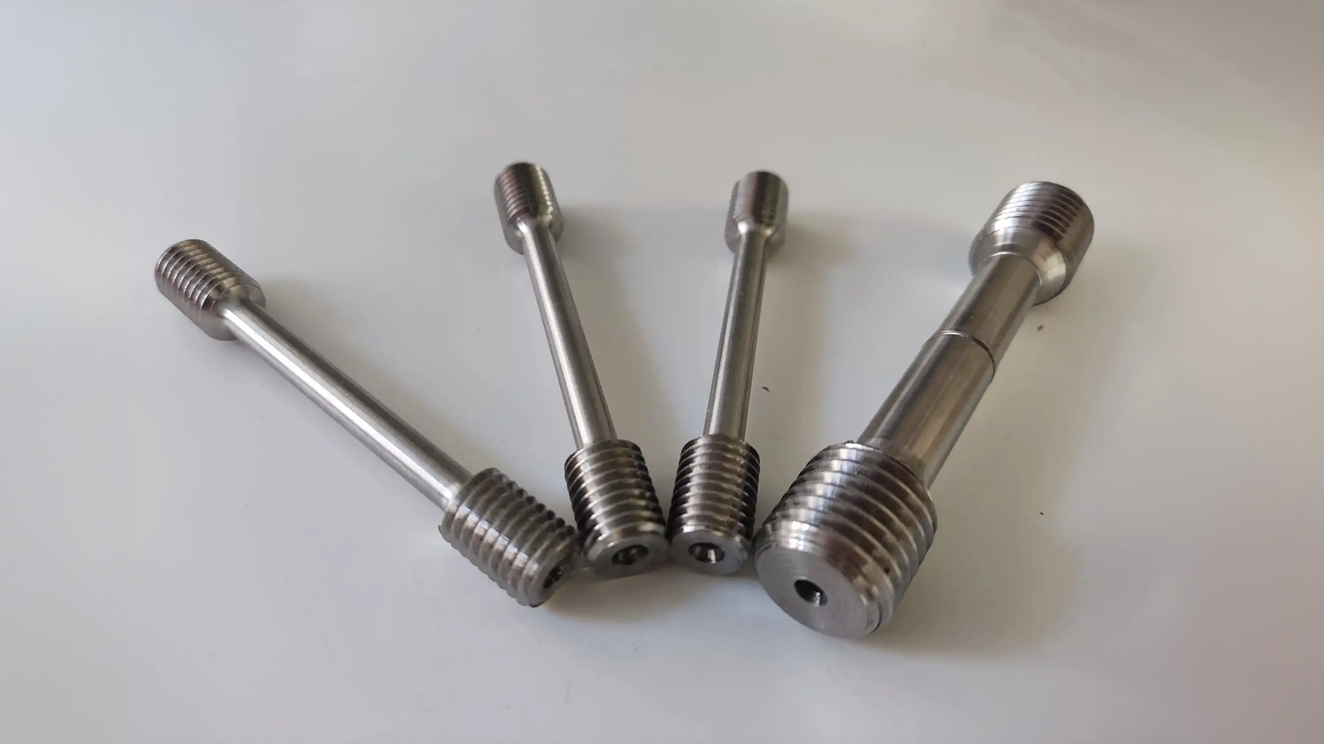
Even small dimensional inaccuracies, surface roughness, or undetectable edge flaws in tensile specimens—that is, even minor deviations in test results—can have a major impact. Whether the testing machine is precise or not, these defects usually result in early fracture, shortened elongation, or data inconsistency.
Still, there are not many large-scale studies measuring the actual impacts of specimen preparation quality. Most accessible knowledge comes from only a few experiments or from inside laboratory experience.
The thorough review of 1000+ tensile test reports from different laboratories and testing environments forms the core of this work. Reviewing these records helps us to find typical preparation-related problems, measure their frequency, and determine how they affect test dependability. The results are organized based on material type, machining technique, post-processing, storage conditions, and standard compliance, offering a data-driven foundation for improving specimen preparation techniques.
Scope and Methodology of the Study
The dataset for this study includes over 1,000 tensile test reports, each documenting tests performed on metallic specimens prepared and handled under varying conditions. R&D projects, regular production testing, and quality assurance processes carried out in internal labs, customer labs, and certified partner sites produced the reports.
Every report was categorized according to the following criteria in order to enable ordered analysis:
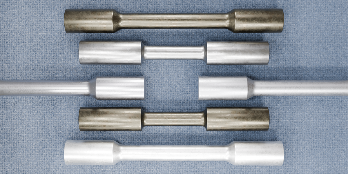
- Material type: The specimens represented common industrial alloys, including carbon and low-alloy steels, austenitic stainless steels (304, 316), aluminum alloys (6061-T6, 7075-T6), and titanium alloys (Ti-6Al-4V). These classifications were chosen to represent an extended range of mechanical characteristics and preparation-related sensitivity.
- Preparation method: Machining processes were classified into CNC milling and turning, manual cutting (e.g., bandsaw, grinding), wire EDM, abrasive waterjet, and laser cutting. Defect frequency, surface quality, and dimensional accuracy were all related to the process that was documented.
- Storage and handling conditions: Reports included environmental data such as temperature, humidity, and time between machining and testing. After being prepared, some specimens were tested immediately, while others were kept for days or weeks in either controlled or uncontrolled environments.
- Machine type used: The tensile tests were conducted on either electromechanical or servo-hydraulic universal testing machines. Both types were included to assess whether equipment configuration influenced the occurrence or detection of prep-related issues.
- Post-processing status: The specimens were categorized according to whether they were tested as-machined or following further procedures like stress-relieving annealing, grinding, or polishing.
- Standard compliance: The procedures referenced in the reports included ASTM E8/E8M, ISO 6892-1, and DIN 50125 for tensile testing; ASTM E4 and ISO 7500-1 for force verification; ASTM E1012 for alignment; and ASTM E83 or ISO 9513 for extensometer calibration.
Important information was gathered from each report. This included the size of the specimen, the method of preparation, the description of the failure, and the tensile results, which included yield strength, ultimate strength, elongation, and fracture location. A report was examined more thoroughly during the analysis if it mentioned odd results, issues with preparation, or unsuccessful tests.
Classification of Preparation-Related Errors and Observed Failure Outcomes
We now move on to an in-depth examination of the main preparation-related mistakes found in the dataset. The following part describes the typical causes of each problem, the most common circumstances in which it arises, and the precise effect that each problem has on the results of tensile tests. We also give a succinct explanation of remedial actions or mitigation techniques for every instance, providing useful advice based on patterns found in the reports under review.
Dimensional Inaccuracies
Dimensional inaccuracies refer to deviations from the required specimen geometry—whether in gauge length, thickness, width, or fillet radius. Tensile performance and stress calculations can be greatly impacted by even small deviations from standard dimensions.
How It Occurs
Usually, cutting or machining introduces these errors. Because of human error and a lack of control, manual techniques like bandsawing and grinding introduce variability. If the machine is miscalibrated, the tooling is worn, or the programming is off, even automated processes like CNC machining can have problems. Off-spec geometry may also be the consequence of dimension conversion errors or the use of non-standard templates.
When It Shows Up During Testing
Unexpected tensile behavior is frequently a sign of dimensional problems. Premature fracture or yielding may occur in specimens with a smaller cross-sectional area. Large specimens have the potential to shatter outside the gauge region, especially at the shoulder or transition radius. Particularly for elongation measurements, such outcomes could result in inaccurate data.
Frequency in Dataset
Dimensional non-conformities were reported in about 5–8% of the examined reports. Approximately 2% were severe enough to invalidate the test. Interestingly, dimensional problems were roughly twice as prevalent in manually prepared samples as in CNC-machined samples.
Common Failure Modes
The most frequently observed outcomes include:
- Early gauge fracture brought on by undersized sections
- Failure due to geometric mismatch outside the gauge or close to the grip
- Inaccurate stress estimation brought on by false area assumptions
- Stress concentration at geometric anomalies results in decreased elongation readings.
Resolution
To minimize dimensional inaccuracies:
- For specimen preparation, use precise CNC machining.
- Maintain appropriate, sharp cutting tools and calibrate machines on a regular basis.
- Use calipers, micrometers, or optical comparators to perform dimensional inspections.
- Pay attention strictly to standard drawings and tolerances (e.g., ASTM E8, ISO 6892).
- Any specimen that fails dimensional checks should be disqualified and replaced.
Surface Finish Irregularities
Surface finish irregularities are a frequently overlooked but impactful issue in tensile specimen preparation. Even when other dimensions are within tolerance, these defects may serve as early crack initiation sites, especially in the gauge section, producing distorted results.
How It Occurs
Usually, surface flaws start during the cutting or machining process. Heat-affected zones (HAZs) are introduced by laser cutting, striations or recast layers may be left by EDM and abrasive waterjet processes, and chatter marks, burrs, or micro-notches may result from mechanical sawing or milling if tooling is worn out or parameters are off. Uncontrolled manual filing or grinding can also result in surface hardening or scratches.
When It Shows Up During Testing
These defects frequently show up as localized failure points when subjected to tensile load. If extensometers are placed on rough or uneven surfaces, they may slip or detach, and premature fracture may occur without the anticipated necking phase. Additionally, surface-induced stress concentrations can decrease elongation or distort the stress-strain curve.
Frequency in Dataset
About 5% of the studied reports had surface finish problems. They were more common in samples made by hand cutting, waterjet, or EDM. On the other hand, there were substantially fewer surface-related failures in specimens that were CNC-machined and then polished.
Impact on Fracture Behavior
Early fracture initiation, usually at micro-notches or burrs, may occur from inconsistent or subpar surface finishes. These specimens frequently show less variation in strength and ductility among ostensibly identical samples. Sometimes surface-level fractures may occur before complete plastic deformation, leading to deceptively low elongation values.
Common Failure Modes
The following failure outcomes are most frequently caused by surface finish defects:
- Surface flaws that fracture too soon before uniform necking
- Early crack initiation results in lower measured elongation.
- Inaccurate data on tensile strength for comparable specimens
- Problems with the extendometer's attachment or signal loss during the test
Resolution
The following actions are advised in order to resolve and avoid surface finish problems:
- Use post-machining finishing techniques such as vibratory deburring, polishing, or grinding.
- Replace worn-out tools as soon as possible and use the right cutting parameters.
- Avoid doing surface finishing by hand unless you are a skilled technician.
- Before testing, examine the gauge section visually and under a microscope.
- Based on best practices, aim for a surface roughness Ra of less than 2 µm in metallic specimens.
Edge Defects and Notching
Small flaws at the specimen edges can be more difficult to spot but can be just as harmful, even though surface finish and geometry are frequently examined during specimen preparation. Particularly in high-strength or brittle materials, these localized defects—like notches, nicks, or microcracks—often serve as stress concentrators and greatly raise the risk of early fracture.
How Edge Flaws Happen
In contrast to surface roughness or dimensional errors, edge defects are frequently the result of localized events such as aggressive deburring, close spacing between blanks, abrupt tool exit during cutting, or improper handling during transportation. Subtle damage can result from even minor edge impacts, like a dropped specimen or an overtightened clamp. In specimens cut from sheet stock or processed with high-energy tools like lasers and EDM, where melt-back or abrupt transitions may form along the profile, edge quality is especially sensitive.
How and When They Affect Tests
Edge imperfections typically have a greater impact on the fracture process than initial loading, as is the case with inadequate surface finish. Once the specimen experiences plastic deformation, it typically becomes critical. These defects' notch-like behavior diverts stress to a specific location, frequently starting fractures before uniform necking can take place. Unnoticed edge flaws in tests can cause them to pass dimensional checks and appear acceptable until they prematurely fail and invalidate the results of elongation.
Documented Frequency
About 2-3% of all reviewed reports specifically mentioned edge-related issues. Fracture surface analysis, however, showed features—like angled breaks or initiation from specimen margins—that point to a higher true incidence, possibly close to 5%, in reports without evident prep errors. The strongest association with this failure mode was found in reports with edges that were hand-cut, shear-cut, or thermally processed.
Resulting Failures
Most frequently, the existence of edge defects resulted in:
- Fracture that starts from the specimen's edge instead of its center
- Reduced elongation values as a result of necking suppression
- Brittle failure in ductile materials that is not representative
- Breaks outside the gauge region result in test invalidation.
Resolution
Some measures are recommended to lessen the possibility of edge-related problems:
- To avoid edge crowding, keep enough distance between cuts.
- Before testing, examine all specimen edges at a magnification of at least 10×.
- Gently deburr edges to avoid creating new blemishes or scratches.
- Any specimen with obvious edge flaws or handling damage should be rejected and replaced.
Material Contamination or Oxidation
Although frequently overlooked, specimen contamination or surface oxidation was identified in multiple reviewed reports as a significant source of testing variability. Even though they are minor, these problems can introduce early crack initiation sites, change grip friction, or compromise surface integrity, all of which can skew tensile results.
Mechanism and Cause
Contamination frequently happens as a result of incorrect cleaning or post-machining handling. Dust, airborne particles, fingerprints, and leftover machining fluids can all stick to the specimen's surface. Long-term exposure to air in uncontrolled conditions, particularly at high temperatures or humidity levels, usually causes oxidation. Particularly exposed carbon steels can rust lightly in a matter of days, and titanium and aluminum can discolor or form oxide films if not stored properly.
Environmental Conditions That Promote It
Several conditions were most frequently associated with contamination and oxidation in reports:
- Over 60% relative humidity during prolonged storage
- Variations in temperature or persistently high temperatures (>30°C)
- UV exposure or direct sunlight
- Handling without gloves (for example, fingerprints or perspiration residue)
- Storage on outdoor shelves without sealed packaging or desiccants
While less often observed, moisture absorption also had an impact on certain composite and plastic specimens.
Prevalence in Reports
Between 2 and 3 percent of the dataset reported visible oxidation or surface contamination at the time of testing. These were typically observed during either the pre-test examination or the post-test fracture analysis. Pre-test cleaning protocols were included in some reports, demonstrating awareness and mitigation efforts.
Effects on Test Results
Depending on the kind of material and its degree of contamination or oxidation, the following are some of the effects:
- Decreased elongation, particularly if microcracks are caused by surface pits or oxide films
- Changes in gripping behavior, such as increased grip force or slippage brought on by oil or residue
- Surface embrittlement following prolonged exposure, especially in titanium or high-strength steels
- Extensometer signal interference brought on by inadequate surface contact or film layers
Resolution
To minimize contamination or oxidation issues, the following practices were identified as effective across the dataset:
- Keep specimens in desiccant-filled bags or sealed containers in conditions with less than 50% relative humidity.
- During and after machining, wear gloves or use clean tools to prevent bare-handed handling.
- To get rid of oils or machining residues, clean every gauge section with acetone or alcohol.
- Examine surfaces visually before testing; replace or rework any specimens that have deposits or discoloration.
- Light polishing or chemical cleaning can be used to restore the surface condition of delicate materials without changing their geometry.
Residual Stresses from Improper Machining
Residual stresses are internal forces locked within a specimen as a result of cutting, shaping, or finishing processes. Even though they cannot be seen or measured directly without specialized methods, they have a big influence on tensile testing, especially for high-strength alloys where even small surface stresses can change the results of yield, elongation, or fracture.

Why They Form
During the machining process, residual stresses usually result from either mechanical deformation or uneven thermal cycling. High-speed grinding, aggressive milling, and turning without coolant can cause localized heat buildup or plastically deform surface layers. Despite their accuracy, processes like EDM and laser cutting are known to result in heat-affected zones and recast layers. Asymmetrical stress fields may also remain throughout the gauge section as a result of uneven material removal or inadequate finishing passes.
How They Manifest During Testing
During tensile testing, these stresses interact with loads that are applied externally. By basically "pre-loading" the specimen, tensile residual stresses can lower the apparent yield strength. On the other hand, compressive residual stresses may increase strength readings and postpone yielding. Additional signs include the specimen's initial curvature or bowing, non-linear stress-strain behavior at low strains, or early localized deformation, particularly on one side of the gauge. Underlying stress effects were indicated by test curves that showed uncharacteristic yield points or poor repeatability across similar specimens.
Dataset Occurrence
Residual stress has been identified as a contributing factor in only 1-2 percent of the reviewed reports. Indirect evidence, however, points to a wider impact. Minor post-machining warping or odd fracture behavior that cannot be attributed to surface or geometric defects was reported in a number of cases. Furthermore, labs that used thermal stress relief consistently reported improved batch-to-batch repeatability, suggesting that untreated specimens might have had residual stress variations even if they weren't officially diagnosed.
Failure Consequences
The following are the most frequently reported related effects, based on the reviewed data:
- Early fracture or premature yielding as a result of concentrated tensile stress
- Readings of yield strength that have been artificially increased or decreased
- One-sided or off-axis fractures are frequently associated with uneven surface stress fields.
- Stress-strain curves that are irregular or non-reproducible make it more difficult to interpret the results.
Although these problems rarely make all tests completely invalid, they do decrease data reliability and increase result scatter, which can be especially troublesome in high-precision or certification applications.
Resolution
The impact of residual stresses caused by machining can be reduced by a number of corrective measures. The following metrics were either suggested by literature and standards or found in the dataset:
- When the material's properties allow, follow rough machining with a low-temperature stress-relieving annealing cycle.
- Control heat input during milling or turning by using the appropriate coolant flow and cutting speeds.
- Reduce the use of asymmetrical or aggressive cuts and instead favor balanced machining techniques.
- To remove impacted layers, post-machine grind the gauge area after thermal cutting.
- After machining, let the specimens sit at room temperature to allow for partial stress relaxation.
- Remove specimens that are warped from testing by identifying them visually or using flatness gauges.
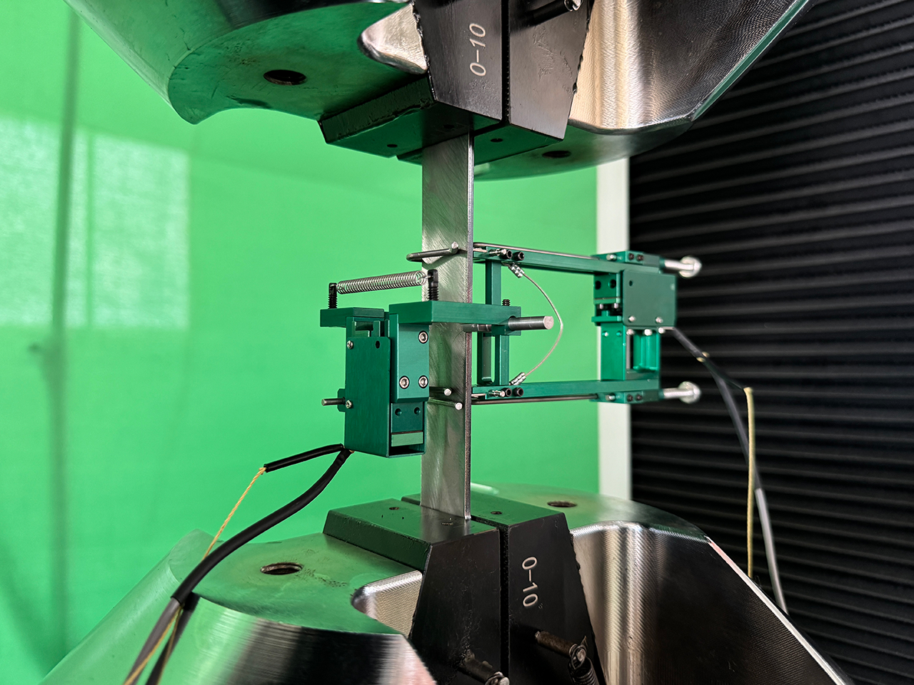
Poor Alignment During Gripping
To guarantee that tensile force is applied consistently along the specimen's axis, alignment during gripping is a must. The accuracy of stress and strain measurements can be greatly impacted by even small deviations since they can introduce bending stresses. Even though it can be subtle at times, this problem was noted in several reports and is particularly important when working with high-strength or brittle materials.
Cause
Either procedural errors or equipment limitations can cause misalignment. Asymmetrical or antiquated grip designs, worn grip faces, incorrect specimen centering during loading, and a lack of self-aligning fixtures are common causes. Angular misalignment is especially likely to occur in older test frames without pivoting grips or spherical seatings. Uneven load distribution can occasionally result from one side of the specimen engaging too soon due to even a small tilt during tightening.
How It’s Detected
One of two approaches is usually used to detect misalignment: either post-test analysis of fracture patterns or direct measurement of bending strain using strain-gaged alignment fixtures (as described in ASTM E1012). Fracture happens symmetrically in the gauge section of well-aligned specimens, frequently with uniform necking. On the other hand, specimens that are misaligned might exhibit asymmetric or angled breaks, like fractures near the grip shoulder or one-sided 45° shear lips. In order to deduce potential bending, some labs also use extensometer readings or notice odd initial stress-strain behavior (such as inconsistent modulus).
Frequency
About 2–3% of the reports specifically mentioned poor alignment, either by means of formal alignment checks or by looking back at atypical fractures. Nearly zero cases of bending-related anomalies were reported from labs that used contemporary electromechanical machines with self-aligning grips. On the other hand, when testing long, narrow, or stiff specimens, facilities with outdated servo-hydraulic frames or little alignment verification displayed more occurrences.
Associated Test Anomalies
In tests impacted by poor alignment, the following abnormalities were commonly noted:
- Fracture outside the gauge area, frequently close to the grip shoulders
- Asymmetric fracture surfaces that show both tensile and bending failure
- Decreased elongation measurements as a result of one side failing too soon
- Inaccurate strain or modulus measurements, especially in the curve's early phases
- Extensometers that are dislodged or broken as a result of uneven specimen deflection
These anomalies reduce the reliability of test outcomes and often require specimen replacement and retesting, adding time and cost.
Resolution
It takes both the right tools and dependable practices to mitigate poor alignment. Throughout the dataset, the following procedures were found to be successful:
- When feasible, use self-aligning grips (such as pivoting jaws or spherical seatings).
- Using strain-gaged dummy specimens in accordance with ASTM E1012, perform routine alignment verification.
- Examine and maintain grip faces on a regular basis to guarantee symmetry and cleanliness.
- When loading, carefully center the specimen so that it aligns laterally and vertically.
- To guarantee uniform insertion depth, mark the grip engagement areas on the specimens.
- Train technicians to recognize the first indications of misalignment and to regrip as needed.
Specifically, those who used alignment verification tools recorded bending strains below 5%, which is well within permissible bounds for testing of high quality.
Environmental Degradation from Improper Storage
Environmental damage that occurs during storage is the last category in our classification, which addresses a less obvious but no less significant source of test variability. Improper storage conditions can gradually change a specimen's surface or internal properties, especially in metals that are prone to oxidation or moisture-sensitive polymers, though they are less obvious than machining flaws or misalignment. This final section explains how this type of degradation arises, the circumstances in which it occurs, and the quantifiable impact it has on the outcomes of tensile tests.
Forms of Degradation
Slow alterations to the specimen's surface or subsurface brought on by exposure to contaminants, light, humidity, or temperature are typically the cause of environmental degradation. This can include moisture absorption, embrittlement, or UV-induced aging for polymers and composites, and surface oxidation or hydrogen absorption for metals. These modifications affect how the material behaves under load and might not be noticeable right away without close examination.
Examples of Contributing Conditions
The key environmental factors that made a contribution based to the reviewed reports, were:
- High temperatures (such as those above 30 °C for prolonged periods of time) can hasten the aging process of age-hardenable alloys or push oxidation in reactive metals.
- High relative humidity (above 60%) can cause steel to corrode or polymers like nylon to absorb moisture.
- UV exposure usually affects non-metallic specimens that are kept in direct sunlight.
- Long-term storage can cause drying in polymers or natural aging in some alloys, which can reduce their toughness or flexibility.
In some cases, specimens were kept on open shelves for weeks or months before being tested, particularly in settings without climate control.
Statistical Relevance
About 2% of the reports specifically addressed environmental storage-related concerns. Indirect evidence, however, like surface rust, decreased ductility, or uneven performance within the same batch, indicates that the true frequency might be a little higher, especially in labs with lax storage regulations. While some industrial labs testing older stock material demonstrated obvious surface changes, aerospace and defense labs with controlled storage environments reported almost no degradation effects.
Effects on Strength and Ductility
Environmentally deteriorated specimens showed:
- Slightly lower elongation values, usually as a result of corrosion-induced stress risers or surface embrittlement
- Tensile strength that is lower or more variable, particularly in older or UV-damaged polymers
- Results are more dispersed, which makes it more difficult to spot real material trends.
- Sometimes tests were invalid because corrosion caused premature fracture in unexpected places.
Interestingly, even in the absence of obvious corrosion, some high-strength titanium and aluminum alloys displayed a 2–5% decrease in ductility following extended high-temperature storage.
Resolution
To reduce the deterioration of the environment:
- All specimens should be kept in conditions with controlled temperatures and humidity (e.g., 20–23 °C, <50% RH).
- For long-term storage or sensitive materials, use desiccators or sealed containers.
- Use storage cabinets or opaque covers to shield non-metallic specimens from UV light.
- Establish a policy for the maximum amount of time that specimens can be stored, and revalidate any that are kept for longer than that.
- Prior to testing, clean the specimens to get rid of any obvious oxidation, dust, or residue.
- Think about including storage conditions in the test record for important materials.
Standard Certification Contribution to Test Reliability

The correct calibration and certification of the testing systems themselves are also needed for long-term reliability, even though specimen preparation is crucial for test accuracy. The exact purpose of standards like ASTM E4, ISO 7500-1, ASTM E1012, and ISO 9513 is to guarantee alignment control, traceable force verification, and extensometer calibration—all of which have a substantial influence on the results of tensile tests.
In its turn, we at TensileMill CNC offer complete assistance in reaching and preserving compliance with ASTM, ANSI/NCSL Z540-1-1994, ISO/IEC 17025:2017, and NADCAP standards. We facilitate equipment certification for both our own systems and third-party devices, such as universal testing machines, extensometers, and specimen preparation equipment, through our collaborations with labs that have earned ISO 17025 accreditation.
In addition to calibration, we provide precision alignment tools and operator training to help clients get ready for audits under NADCAP accreditation. In addition to meeting technical requirements, these services improve process consistency, minimize retesting, and guarantee that all measurements are both justified and accepted by the industry.
Certification is an important aspect of data credibility for labs and manufacturers working in high-stakes settings, such as aerospace, defense, or regulated manufacturing. At each step of the testing process, TensileMill CNC provides dependable, certified performance in support of this goal.
Connecting Practice and Observations for Accurate Testing Results
A consistent finding is highlighted by this thorough examination of more than 1,000 tensile test reports: the quality of specimen preparation and carefully monitored test conditions have a significant impact on the dependability of tensile test results. Every factor, no matter how minor, can significantly skew mechanical data and undermine the trustworthiness of material performance evaluations, from surface imperfections and dimensional irregularities to alignment problems and storage-related deterioration.
This study is unique not only because of the size of its dataset but also because of its ability to convert dispersed observations into organized knowledge. We can better understand how and why deviations happen—and, more importantly, how to prevent them—by classifying preparation errors in a systematic manner and connecting them to actual failure modes. Furthermore, the data shows that post-processing procedures, environmental protections, and controlled machining techniques—especially CNC-based preparation—have a strong correlation with more reliable and consistent results.
However, the calibration and certification of the tensile testing equipment is equally as important as specimen quality. Inaccurate force readings, misaligned grips, or unreliable extensometers can introduce errors of their own regardless of how well a sample is prepared. Following international standards like ASTM E4, ISO 7500-1, ASTM E1012, and ISO/IEC 17025 is a necessity for maintaining data integrity for internal validation as well as for regulatory compliance and audit-readiness.
Our goal at TensileMill CNC is to assist manufacturers and labs in achieving the highest standards of testing reliability. Our staff is available to assist you whether you need certification services for already-existing equipment, advice on how to align with NADCAP or ISO standards, or want to purchase precise, compliant tensile testing systems. Get a quote online or get in touch with us directly. We are prepared to assist you in selecting the best option for your particular testing environment.