Standards Compliance: ASTM E4, ASTM E8, ASTM F606, ASTM E92, ASTM A370, ASTM E21, ASTM D3039, ISO 6892-1, ISO 6892-2, ISO 7500-1, ISO 527, ISO 9513, EN ISO 15630-1, EN 10002-1


Description
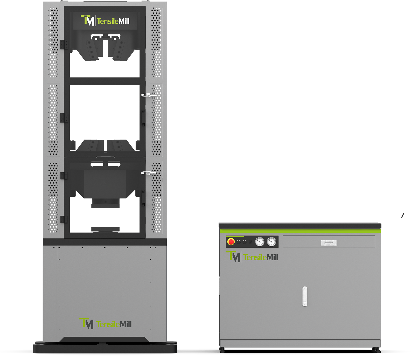
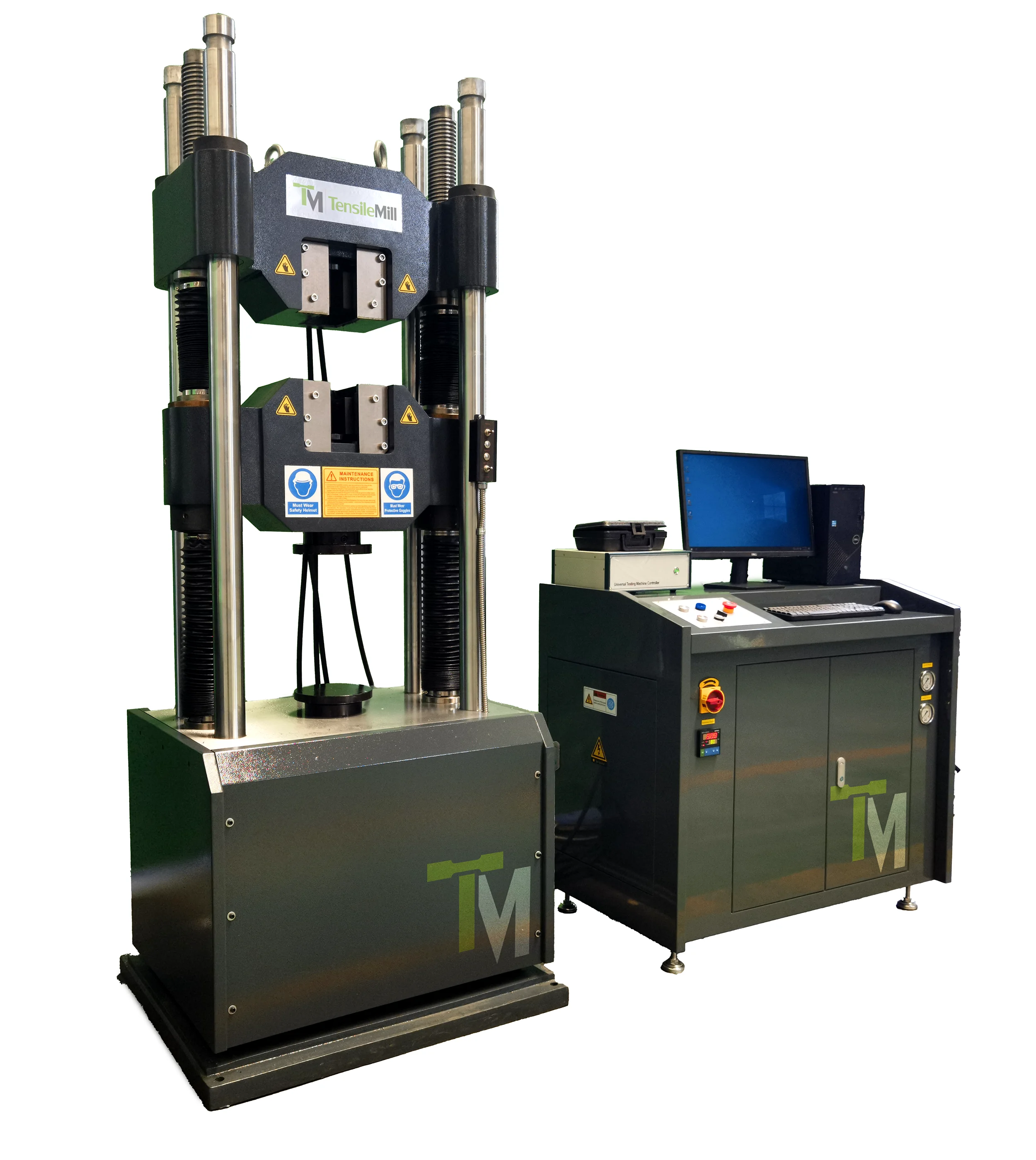
The TM-SHM Series A Servo-Hydraulic Universal Testing Machine (300 kN - 3000 kN) is a high-force static tensile and compression testing system for metallic specimens used in material testing, quality control, production monitoring and certification workflows. The servo-hydraulic actuator delivers controlled loading for large cross-section samples, while the multi-column load frame maintains alignment during high-force tensile, proof and compression testing. This UTM follows the requirements of ASTM E8, ASTM A370, ISO 6892-1, ISO 7500-1 and related standards used in industrial metal evaluation.
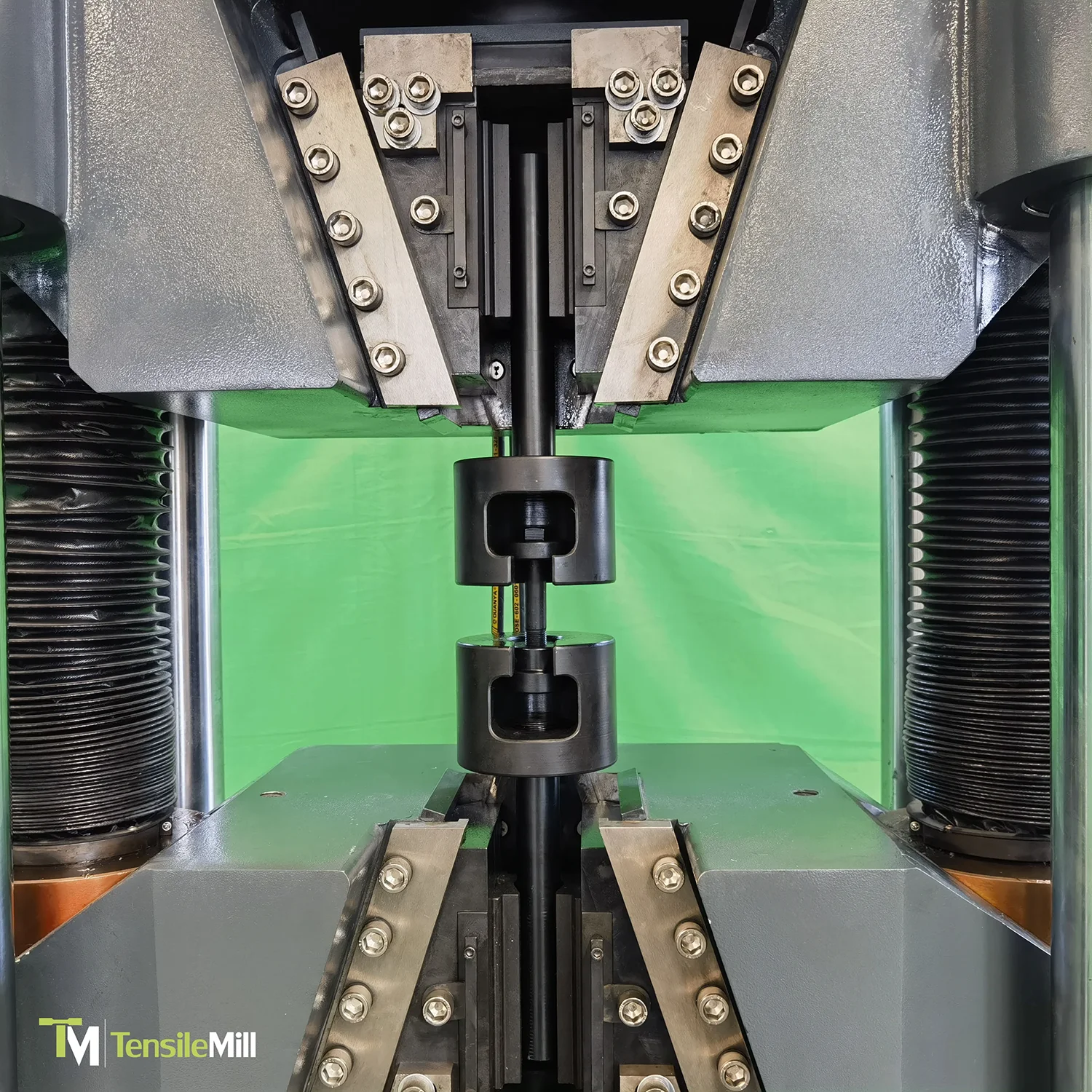
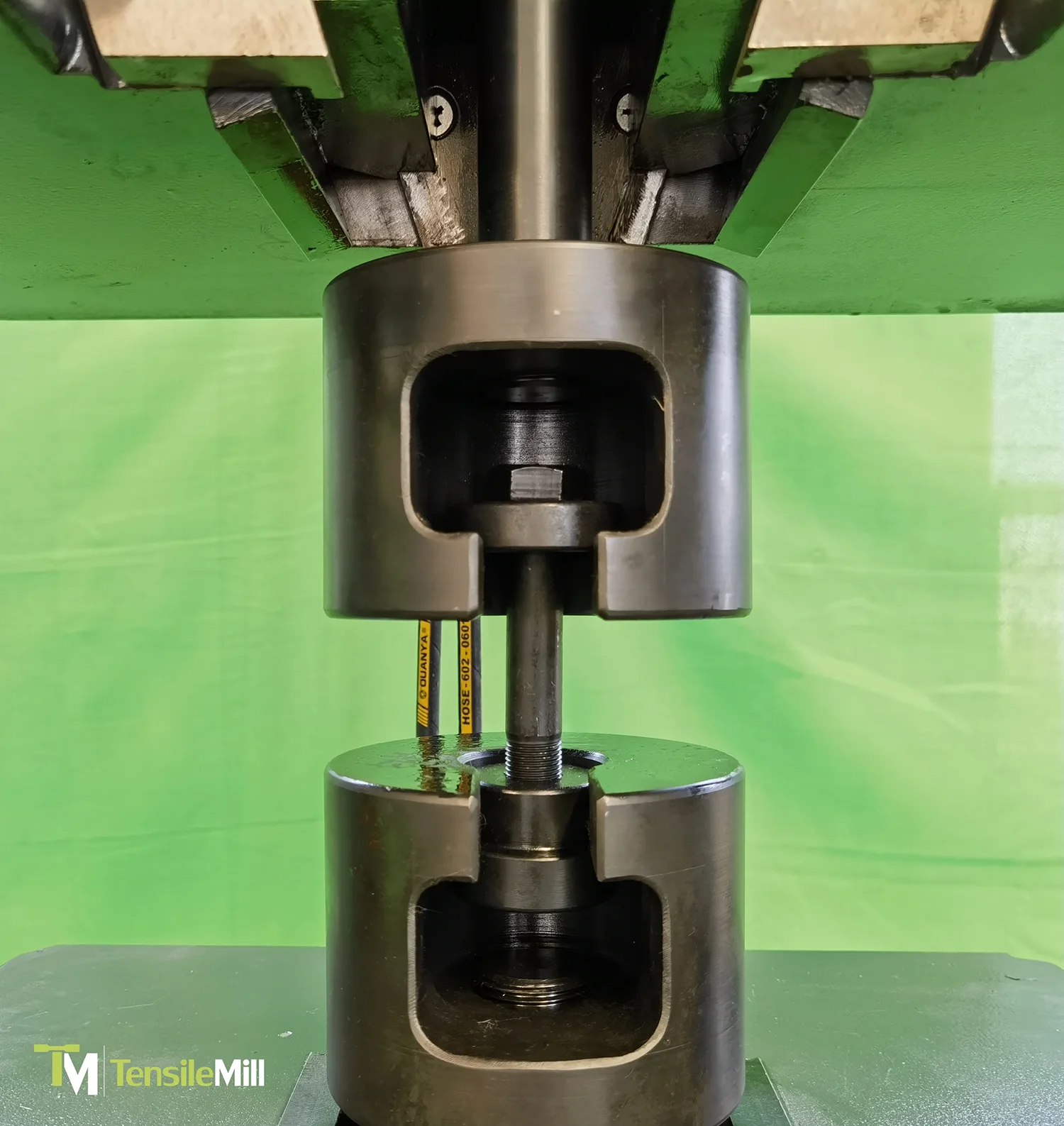
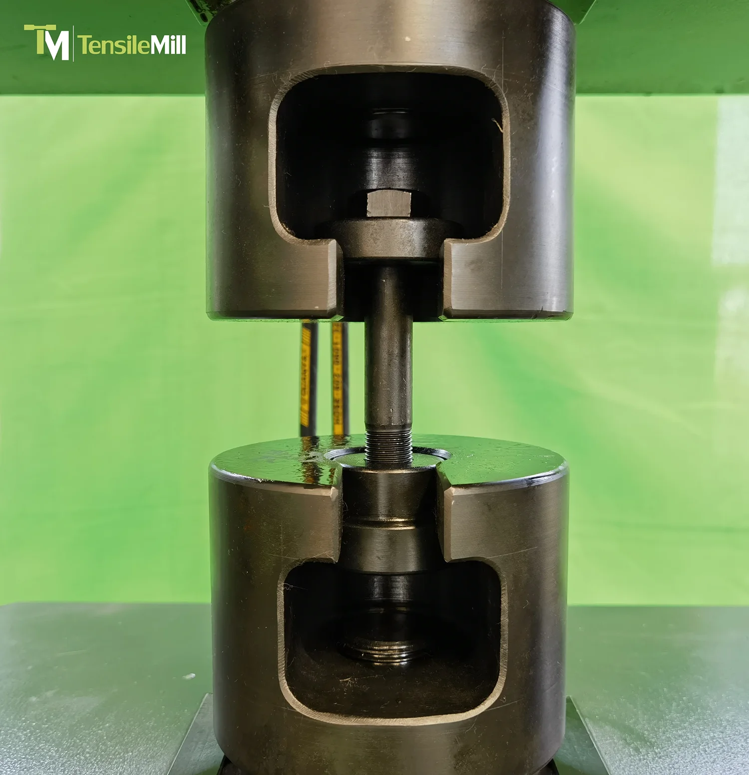
A dual-zone test arrangement supports tension testing on the upper crosshead and compression testing on the lower platen with a fixed upper tension and lower compression station. This layout reduces handling time in repetitive workflows and supports common procedures used in rebar testing, fastener evaluation, bar and wire inspection and welded joint qualification. Load measurement is performed through a high-resolution strain-gauge system located in the lower fixture area, with calibration practices consistent with ASTM E4. The hydraulic unit uses pressure-following regulation with screw-pump flow, providing smooth and pulse-free operation under varying load conditions.
Force Capacity: 300 kN, 600 kN, 1000 kN, 2000 kN, 3000 kN (67,400 - 674,400 lbf)
Frame Configuration: Multi-column servo-hydraulic load frame with crosshead positioning
Test Space: Dual-zone (upper tension / lower compression) layout with reduced fixture handling
Typical Applications: Rebar, fasteners, bar and wire, welded joints, cast components
Universal Testing Machine - Bending Test
Applications & Typical Specimens
The TM-SHM Series A is used for static tensile and compression testing of metallic materials in material testing laboratories, QA departments and industrial production facilities. Typical applications include tensile qualification per ASTM E8, mechanical property evaluation per ASTM A370, static loading procedures under ISO 6892-1, and rebar inspection following EN ISO 15630-1. The system supports routine batch verification, mill testing, welded joint assessment and component-level evaluation for industrial metal products.
The machine accommodates medium- to large-scale metallic specimens and structural elements requiring high-force loading. Compatible specimens include:
- Rebar, threaded bar, smooth bar and structural rod
- Plates, billets, thick sheet material and machined test coupons
- Steel wires, cables, chains, anchoring hardware and lifting components
- Welded joints, welded plate sections and heat-affected zones
- Cast and forged components, brackets and industrial metal housings
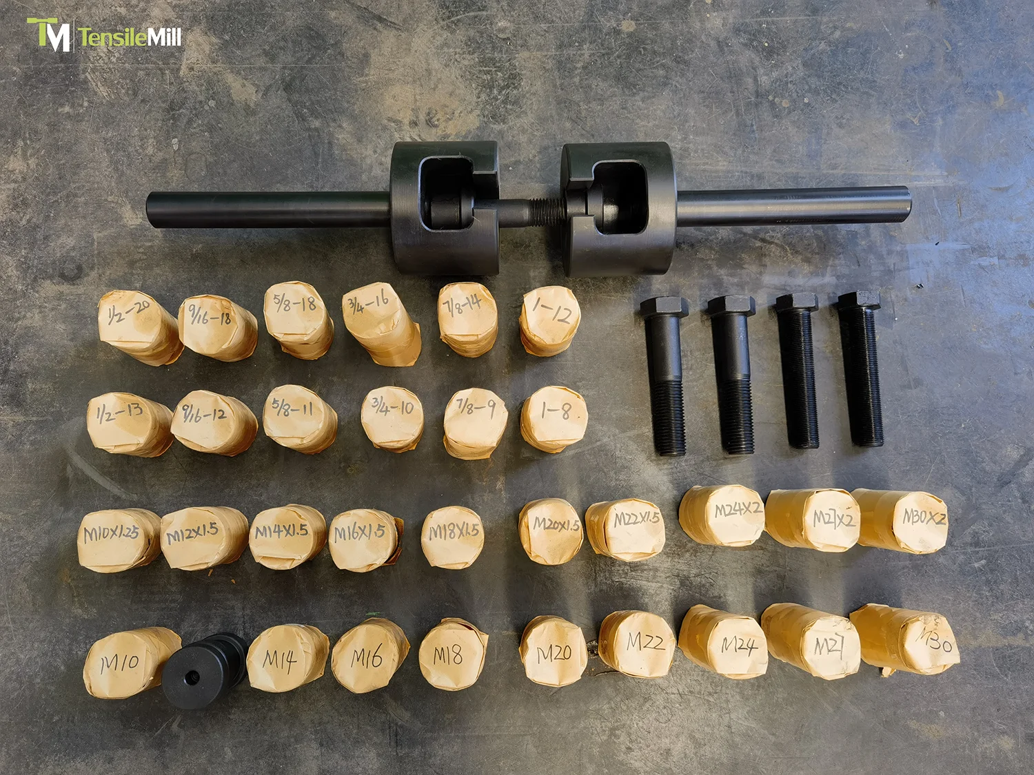
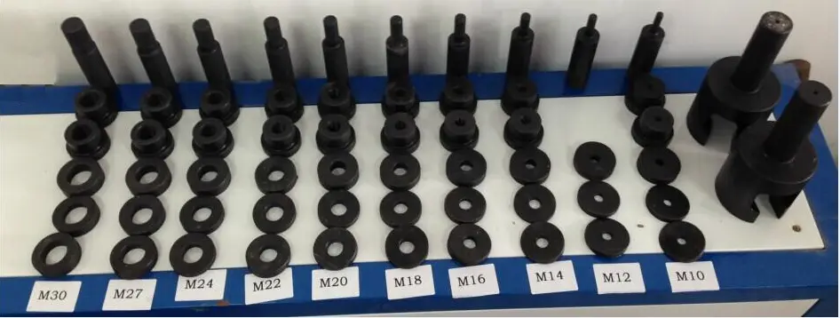
- Bolts, nuts, studs, fasteners and mechanical couplings
- Pipe segments, round bar, tubes, hollow cylinders and various cross-section profiles
- Compression blocks, load-bearing plates and die-forged elements
- High-strength alloys, carbon steels, stainless steels, tool steels and iron-base materials
- Tensile and compression samples prepared according to ISO 6892-1, ASTM E8 and ASTM E9 requirements
Key Features
Below is a consolidated set of key functional characteristics of the TM-SHM Series A:
- Multi-Column Servo-Hydraulic Load Frame: Rigid 4- or 6-column construction with reinforced structural members for reduced deflection during high-force tensile and compression testing.
- Dual-Zone Test Configuration: Separate upper tension and lower compression stations available simultaneously, reducing handling time for repeated tensile-compression workflows.
- Lead-Screw Crosshead Positioning: Controlled vertical adjustment of the test space with precision guides for stable crosshead alignment under load.
- High-Resolution Force Measurement: Strain-gauge load cell installed in the lower fixture area, capturing tension and compression forces with a resolution of 1/500,000 FS; calibration consistent with ASTM E4.
- Pressure-Following Hydraulic Regulation: Hydraulic system with cartridge logic valves and screw-pump flow delivering smooth, pulse-free pressure response under varying load conditions.
- Low-Noise Hydraulic Pumping System: Screw-pump design minimizing hydraulic pulsation and reducing operating noise in continuous test environments.
- High-Efficiency Filtration and Cooling: Multi-stage 5 μm filtration protecting servo components, combined with an automatic air-cooling system for thermal stability during extended operation.
- Servo Valve Control Architecture: High-performance servo valve enabling accurate force and displacement control with low hysteresis and fast pressure response.
- Digital Controller: 6-channel 24-bit data acquisition, up to 1200 Hz control frequency, support for encoder feedback, closed-loop control modes and built-in safety protections.
- GenTest Software Integration: Execution of ASTM and ISO tensile and compression methods with real-time data display, result calculation and report generation.
System Architecture & Load Frame
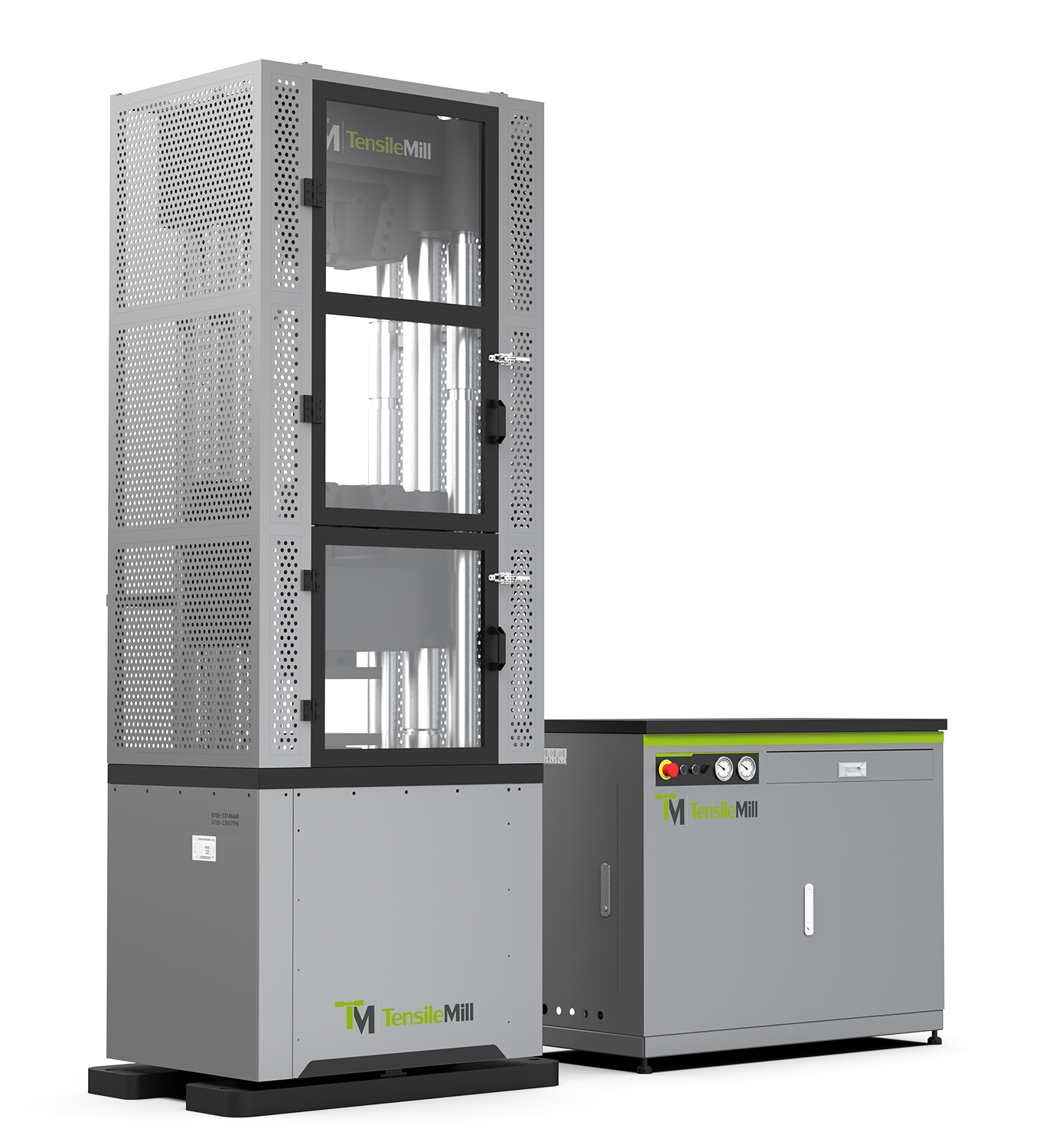
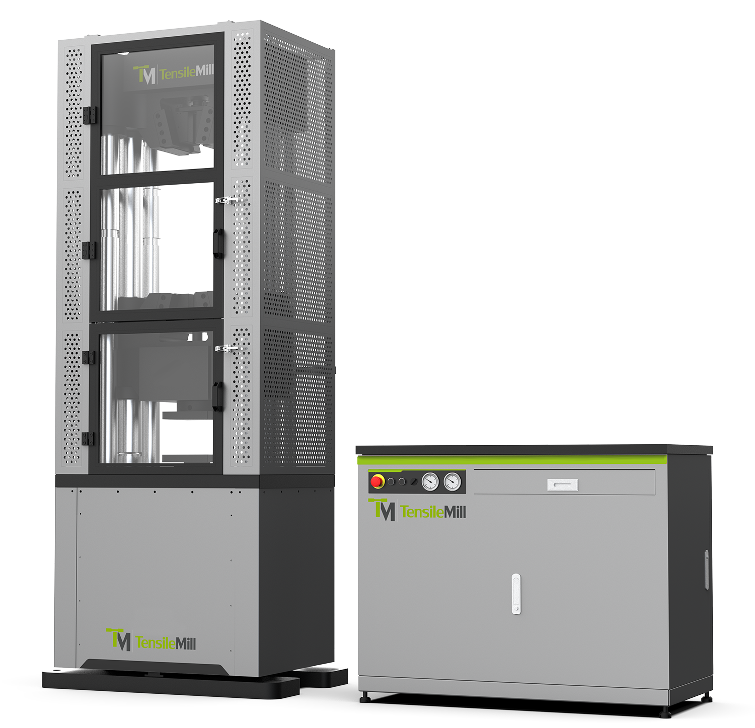
The TM-SHM Series A combines a reinforced servo-hydraulic load frame, an integrated hydraulic power unit and a digital control platform designed for high-force static tensile and compression testing. The structural and hydraulic elements are configured to maintain alignment under load, deliver stable pressure and support the control precision required for ASTM and ISO metal testing procedures.
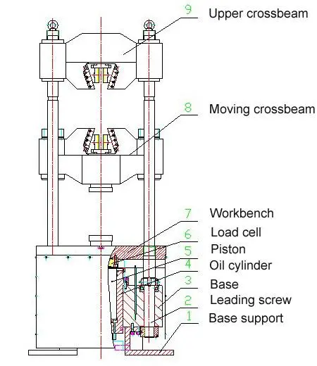
Load Frame & Mechanical Structure
The load frame is built around a 4- or 6-column structure designed to maintain stiffness under high-force loading. Reinforced members limit deflection during tensile and compression testing and provide a stable foundation for measurement accuracy.
Crosshead movement is controlled by a lead-screw adjustment system, allowing consistent vertical positioning of the tensile and compression spaces. The fixed dual-zone layout uses the upper crosshead for tension and the lower platen for compression, supporting standard metal testing workflows.
Key Characteristics
- Reinforced multi-column structure for high-load stability
- Fixed upper tension and lower compression stations
- Lead-screw crosshead adjustment with guided vertical travel
- Alignment maintained throughout the loading cycle
Load Cell Assembly
The system uses a strain-gauge load cell positioned in the lower fixture area to capture both tensile and compression forces directly through the specimen. It operates across the full force range without switching steps and provides a 1/500,000 FS measurement resolution. The design supports repeatable, stable readings required for certification testing.
Key Characteristics
- Direct tensile and compression force measurement
- High-resolution strain-gauge load cell (1/500,000 FS)
- Stable readings without range switching
- Consistent performance for routine and certification workflows
Hydraulic Power Unit (HPU)
The hydraulic power unit supplies the main cylinder and fixture hydraulics through an integrated system designed for stable pressure delivery. It uses cartridge logic valves to regulate working pressure according to real-time cylinder demand. A preset differential (e.g., 2 MPa) is maintained to stabilize transitions during loading.
Pressure Regulation
- Cartridge logic valves for real-time pressure adjustment
- Pressure-following control maintains a preset differential
- Lower output pressure at low load; higher output at increased demand
Screw Pump System
The HPU incorporates screw pumps designed for steady hydraulic output up to 27.5 MPa. The pump provides consistent volumetric delivery and maintains predictable flow characteristics over extended operation.
Key Points:
- Controlled hydraulic output up to 27.5 MPa
- Stable flow with minimal pulsation
- Long service life and low maintenance requirements
Cooling & Filtration
- Automatic air-cooling activation at defined oil-temperature thresholds
- Multi-stage filtration with 5 μm absolute rating
- Protection for servo valves, pump internals and high-pressure components
Maintenance & Safety
- Semi-open enclosure with removable panels for component access
- Relief-valve protection for overpressure events
- High-pressure hoses and cone-seal fittings for reliable sealing
Control System
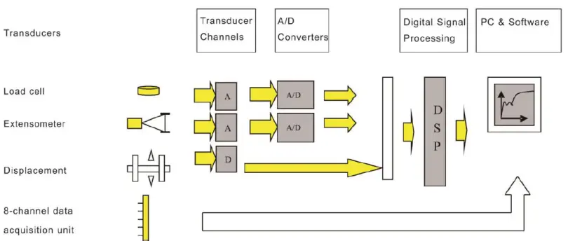
The DTC-500 control platform manages force, displacement and extension through digital closed-loop control. It uses 6-channel, 24-bit A/D acquisition with sampling and control frequencies up to 1200 Hz. Three digital high-speed inputs accommodate encoder or grating-ruler feedback up to 4 MHz, with 20-bit resolution for digital inputs.
Control Architecture
The controller operates independent closed loops for force, extension and displacement. It supports mode switching as required by static tensile and compression test procedures.
Connectivity & Interfaces
The control unit provides USB and Ethernet ports for communication. A dedicated Ethernet processor handles TCP/IP data traffic. Optional dual analog outputs are available for external signal integration.
Safety & Configuration
TEDS support enables automated transducer identification. The controller includes limit protection, overload protection and emergency-stop input circuitry.
Hardware Platform
A 4-layer PCB layout is used to improve noise resistance and maintain signal stability. Locking connectors are employed to secure wiring during continuous testing.
GenTest Professional Test Software
GenTest is a standards-based software platform used for managing tensile and compression tests, configuring method parameters, capturing real-time data and generating structured reports. The system supports ASTM, ISO, DIN and EN procedures commonly used in metal testing, certification workflows and routine laboratory evaluation. Test setup, execution and result calculation follow the requirements of international material-testing standards.
Key Software Features
- Library of pre-configured test methods aligned with ASTM, ISO, DIN and EN standards
- Straightforward method editing for custom test routines or production-specific parameters
- Built-in standard routines for routine tensile and compression testing
- Report templates that allow adding company details, statistics and result fields; export available to Excel or Word
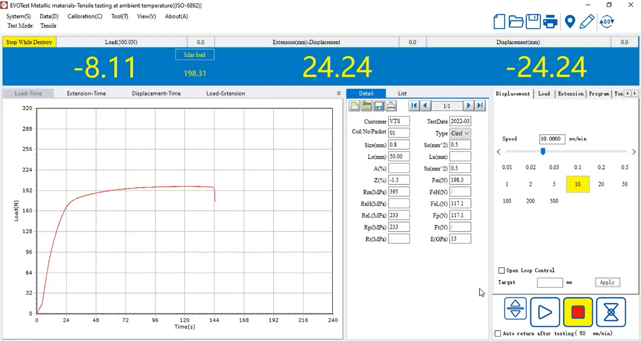
- Real-time curve display, including displacement-load, stress-strain, displacement-time and load-time
- Analysis tools for calculating typical results, including Fm, ReL, ReH, Rp and other values defined by the selected standard
- Flexible unit selection: N, kN, kgf, lbf, MPa and user-defined units via formulas
GenTest: Next-Generation User-Friendly UTM Software | TensileMill CNC
Technical Specifications
The table below presents the full technical specification set for the TM-SHM Series A servo-hydraulic universal testing machines:
| Specification | SHM305 | SHM605 | SHM106 | SHM206 | SHM306 |
|---|---|---|---|---|---|
| Frame Type | Type A | ||||
| Capacity (kN) | 300 | 600 | 1000 | 2000 | 3000 |
| Calibration Accuracy | Class 0.5 | ||||
| Force Accuracy | ±0.5% | ||||
| Force Range | 1% to 100% FS | ||||
| Force Resolution | 1/500000 FS | ||||
| Extension Accuracy | ±0.5% | ||||
| Extension Resolution | 1/500000 of max extension | ||||
| Position Resolution | 0.004 mm | ||||
| Position Accuracy | ±0.5% of reading | ||||
| Actuator Stroke | 5.91 in (150 mm) | 9.84 in (250 mm) | 9.84 in (250 mm) | 9.84 in (250 mm) | 11.81 in (300 mm) |
| Actuator Speed | 0-180 mm/min | 0-140 mm/min | 0-90 mm/min | 0-70 mm/min | 0-100 mm/min |
| Crosshead Speed (adjustment) | 13.78 in/min (350 mm/min) | 10.63 in/min (270 mm/min) | 12.20 in/min (310 mm/min) | 14.17 in/min (360 mm/min) | 9.45 in/min (240 mm/min) |
| Force Loading Speed | 0.05%-2% FS/s | ||||
| Column Number | 4 | 6 | 6 | 6 | 6 |
| Column Spacing (test width) | 16.14 in (410 mm) | 17.13 in (435 mm) | 17.72 in (450 mm) | 28.74 in (730 mm) | 20.87 in (530 mm) |
| Max Tension Space | 20.47 in (520 mm) | 27.95 in (710 mm) | 29.53 in (750 mm) | 35.43 in (900 mm) | 47.24 in (1200 mm) |
| Max Compression Space | 20.47 in (520 mm) | 27.56 in (700 mm) | 29.53 in (750 mm) | 29.53 in (750 mm) | 39.37 in (1000 mm) |
| Round Specimen Ø Range | Ø10-Ø20 mm / Ø20-Ø32 mm | Ø10-Ø21 mm / Ø21-Ø31 mm | Ø12-Ø23 mm / Ø23-Ø35 mm | Ø15-Ø30 mm / Ø30-Ø55 mm | Ø30-Ø70 mm / Ø70-Ø110 mm |
| Flat Specimen Thickness | 2-13 mm / 13-25 mm | 2-16 mm / 16-30 mm | 2-20 mm / 20-40 mm | 10-40 mm / 40-70 mm | 10-60 mm / 60-100 mm |
| Compression Platens Ø | Ø120 mm | Ø150 mm | Ø200 mm | Ø240 mm | Ø280 mm |
| Frame Dimensions (LxWxH) | 32.28 x 22.44 x 76.97 in (820 x 570 x 1955 mm) | 37.01 x 25.59 x 94.49 in (940 x 650 x 2400 mm) | 40.16 x 26.38 x 102.36 in (1020 x 670 x 2600 mm) | 53.94 x 32.28 x 124.02 in (1370 x 820 x 3150 mm) | 52.01 x 37.40 x 155.51 in (1320 x 950 x 3958 mm) |
| HPU Dimensions (LxWxH) | 45.28 x 23.62 x 35.43 in (1150 x 600 x 900 mm) | 45.28 x 24.80 x 39.37 in (1150 x 630 x 1000 mm) | |||
| Hydraulic Power Unit Weight | 661 lb (300 kg) | 882 lb (400 kg) | |||
| HPU Flow Rate (L/min) | 5 | 5 | 5 | 7.2 | 12 |
| Power Consumption (kW) | 2.5 | 3.5 | 4 | 6 | 6 |
| Power Supply | 220 V AC, 50/60Hz | ||||
| Frame Weight | 3307 lb (1500 kg) | 5512 lb (2500 kg) | 7716 lb (3500 kg) | 14991 lb (6800 kg) | 22513 lb (10220 kg) |
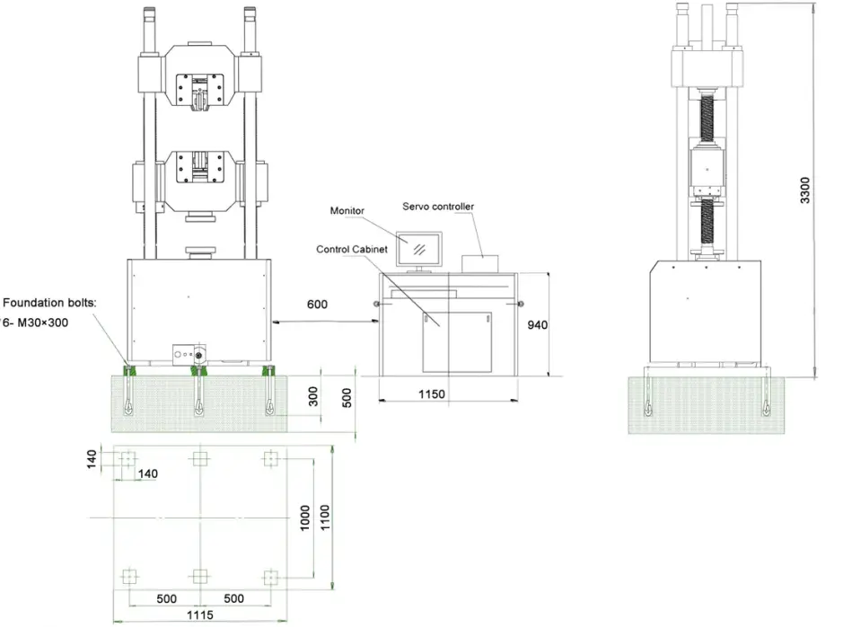
Frame Dimensions
| Model | Outside Dimensions (L x W x H) | Tensile Space (D) | Compression Space (E) | Test Width (F) | Piston Travel |
|---|---|---|---|---|---|
| SHM305 | 32.28 x 22.44 x 76.97 in (820 x 570 x 1955 mm) | 20.47 in (520 mm) | 20.47 in (520 mm) | 16.14 in (410 mm) | 5.91 in (150 mm) |
| SHM605 | 37.01 x 25.59 x 94.49 in (940 x 650 x 2400 mm) | 27.95 in (710 mm) | 27.56 in (700 mm) | 17.13 in (435 mm) | 9.84 in (250 mm) |
| SHM106 | 40.16 x 26.38 x 102.36 in (1020 x 670 x 2600 mm) | 29.53 in (750 mm) | 25.98 in (660 mm) | 17.72 in (450 mm) | 9.84 in (250 mm) |
| SHM206 | 53.94 x 32.28 x 124.02 in (1370 x 820 x 3150 mm) | 35.43 in (900 mm) | 29.53 in (750 mm) | 28.74 in (730 mm) | 9.84 in (250 mm) |
| SHM306 | 52.01 x 37.40 x 155.51 in (1320 x 950 x 3958 mm) | 47.24 in (1200 mm) | 39.37 in (1000 mm) | 20.87 in (530 mm) | 11.81 in (300 mm) |
 - frame at 4m30s.jpg)
 - frame at 5m8s.jpg)
 - frame at 5m39s.jpg)
 - frame at 8m28s.jpg)
 - frame at 9m8s.jpg)
 - frame at 9m59s.jpg)
Video
Universal Testing Machine - Tensile Testing with Extensometer
Universal Testing Machine - Bending Test
GenTest: Next-Generation User-Friendly UTM Software
Why Should I Choose Your Servo Hydraulic Universal Testing Machine 2000 kN?
What After-Sales Support Is Available for Your Universal Testing Machine (UTM)?
What Is the Lead Time for the 2000 kN Servo-Hydraulic UTM?
Does the TensileMill CNC 2000 kN Servo-Hydraulic UTM Meet International Standards?
What Are the Typical Maintenance Costs for the 2000 kN Servo-Hydraulic Universal Testing Machine?
How Do You Minimize Downtime on a Servo-Hydraulic Universal Testing Machine?
What Is the Lead Time for the 600 kN and 1,000 kN Servo-Hydraulic Universal Testing System?
What Are the Maintenance Costs for a Universal Testing Machine?
How Do I Size a Hydraulic Universal Testing Machine for Metals?
What Capacity Hydraulic UTM Do I Need for Steel, Fasteners, and Rebar?
How Do I Size a Hydraulic UTM for ASTM E8 Metals Testing?
How Do I Select The Right Capacity And Configuration For A Hydraulic Universal Testing Machine?
What Specifications Matter When Choosing A Hydraulic UTM For Metals Testing?
How Do I Choose Between Electromechanical and Hydraulic UTMs for Tensile Testing?
How Do I Decide Between Electromechanical And Hydraulic UTMs For My Lab?
How Do I Choose UTM Type And Capacity For Tensile Testing Of Forged Parts?
How Should Forging Labs Size a UTM and Specimen Preparation Setup for Tensile QA?
How Do I Plan an In-House Tensile Testing Setup to Reduce Lab Fees?
How Does Heat Treatment Affect Tensile Testing Setup And Data Quality?
Electromechanical vs Servo-Hydraulic UTMs: How To Choose For Tensile Testing?
How To Choose Between Electromechanical and Servo-Hydraulic UTMs for Tensile Testing
Electromechanical vs Hydraulic UTM: Which Is Right For Metals Tensile Testing?
How Do I Choose Between Electro-Mechanical And Servo-Hydraulic UTMs For Tensile Testing?
How Do I Choose Between Electromechanical And Servo Hydraulic UTMs For Tensile Testing?
People Also Searched For
TensileMill CNC - Classic Upgrade
The TensileMill CNC - Classic Upgrade is the ultimate solution for precise and repeatable flat tensile and impact test specimen preparation. Engineered with TensileSoft™ technology and powered by a Fanuc controller, this machine offers an intuitive, user-friendly experience for both seasoned CNC operators and those with minimal training. Its compact footprint and turnkey design make it an ideal addition to any testing facility, ensuring maximum efficiency without compromising on accuracy. With a high-precision 3.2kW servo motor, the TensileMill CNC - Classic Upgrade is designed to achieve up to 0.0003” accuracy, handling specimens up to 14” long, 2” wide, and 0.5” thick. It meets ASTM, ISO, DIN, and JIS standards while efficiently preparing three 1.0” thick stacks at once with its triple clamping fixture. Compatible with an Impact/Pendulum notching machine, it also streamlines U & V-notch specimen preparation, making it a top choice for precise, high-speed testing.
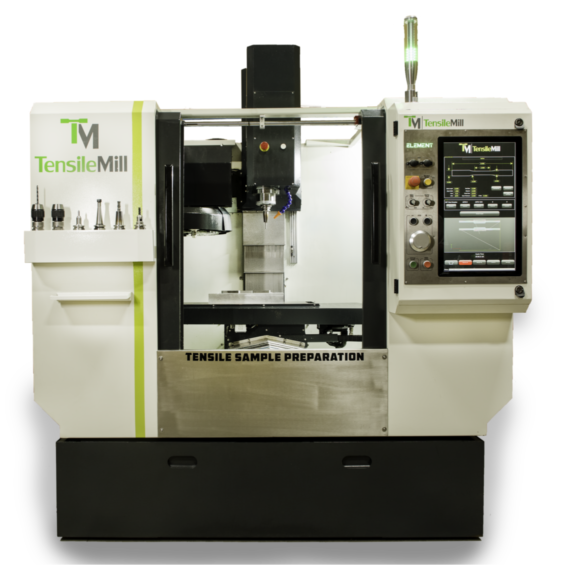
TensileMill CNC XL - Flat Specimen Preparation
The XL model is our larger tensile sample preparation machine that comes standard with an upgrade function of full CNC Carbon package for general purpose CNC requirements. TensileMill CNC XL is equipped with a state-of-the-art auto tool changer for the ultimate milling flexibility and time savings, allowing to prepare various types of tensile specimens and other parts. The advanced software allows to the operator reach milling results in seconds with a push of a few buttons. TensileMill CNC XL is an ideal user-friendly solution for medium to large size laboratories and manufacturing facilities.
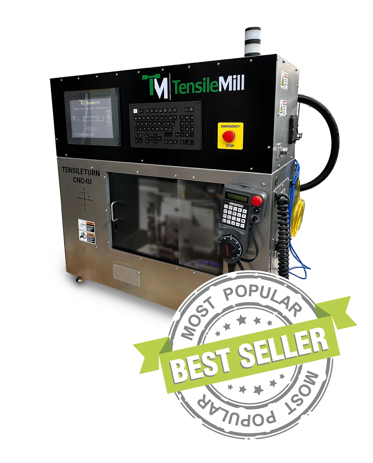
TensileTurn CNC - Industrial Upgrade - Round Tensile Sample Preparation Machine
The Industrial Upgrade model is a substantial step up from our Classic system. It offers the ability to accommodate larger starting blank sizes, tougher materials, irregular shapes, higher specimen preparation volumes, automatic center drilling and other unique functions required for the simplest and most accurate round tensile sample preparation. This system comes standard with a granite frame for added stability and the shock absorption for maximum sample preparation accuracy and longer system life-span. Though the Industrial Upgrade system is extraordinary for tensile specimen preparation needs, it is also capable of full range of CNC machining capabilities.
Tensile Testing Equipment
When selecting a tensile testing machine, there are a number of factors that must be considered. Whether you're upgrading in quality or functionality, or have the decision to move your materials testing in-house, you want to avoid buying a machine that doesn't meet the range of testing or materials for your needs. Of course you will be guided by the type of testing - tensile, compression, fatigue, etc. - and the ASTM or ISO standards for the market your product will enter. Other factors to consider when selecting the perfect tensile tester include…