The marine industry operates in some of the most challenging environments on Earth. Extreme conditions, heavy mechanical loads, and constant exposure to moisture and salt can push materials and equipment to their limits. The safety of employees is a top priority in this field, as even minor material failures can lead to catastrophic consequences, including accidents, costly repairs, and loss of life.
Tensile testing plays a key role in addressing these challenges. It guarantees that shipbuilding, offshore structures, marine equipment materials and components meet the highest safety and performance standards. Tension testing provides critical data on their strength, ductility, and durability. This information is used by engineers and manufacturers when selecting materials, verifying quality, and maintaining safety over the lifespan of marine vessels and equipment.
In this blog, we will investigate how tensile testing has become a fundamental component of safety in the marine industry. We will highlight its applications, benefits, and role as an important component of global standards development
The Role of Tensile Tests in the Marine Industry
Tensile testing is more than just a technical procedure; it is the basis of safety and reliability in the marine industry. This testing method examines how materials respond when subjected to tension, helping to determine their suitability for critical applications in shipbuilding and marine equipment.
Why is Tensile Testing Important in the Marine Sector?
Marine environments are inherently harsh, characterized by constant exposure to saltwater, high humidity, fluctuating temperatures, and intense mechanical stress. Materials used in these conditions must possess exceptional strength and durability to withstand forces such as wave impact, cargo loads, and operational wear. Tensile testing confirms that materials can meet these demands by assessing their yield strength, tensile strength, and elongation.
For instance, high-strength steel used in ship hulls is rigorously tested to confirm its ability to handle stress without permanent deformation. Synthetic fibers used in mooring ropes undergo tensile tests to verify that they can endure repeated load cycles without failure. Marine vessels' structural integrity and crew and cargo safety depend on these tests.
Building Confidence with Valid Data
The data obtained through tensile testing guides engineers and manufacturers in selecting materials that meet specific requirements. This precision reduces material failures, increases product performance, and increases marine operations confidence. Moreover, testing for tensile strength supports compliance with international safety and quality standards, fostering global interoperability and trust in marine equipment and vessels.
Key Applications of Tensile Testing for Marine Safety
The tensile test is most evident in 3 critical areas: material selection, structural integrity in shipbuilding, and quality assurance of marine equipment. Each of these applications addresses specific challenges faced in the harsh and unpredictable marine environment.
1. Material Selection for Marine Environments
Marine environments impose high demands on materials, including exposure to corrosion, fatigue, and mechanical stress. Material selection for marine use is subjected to tests of tensile strength to verify that it meets the performance standards required.
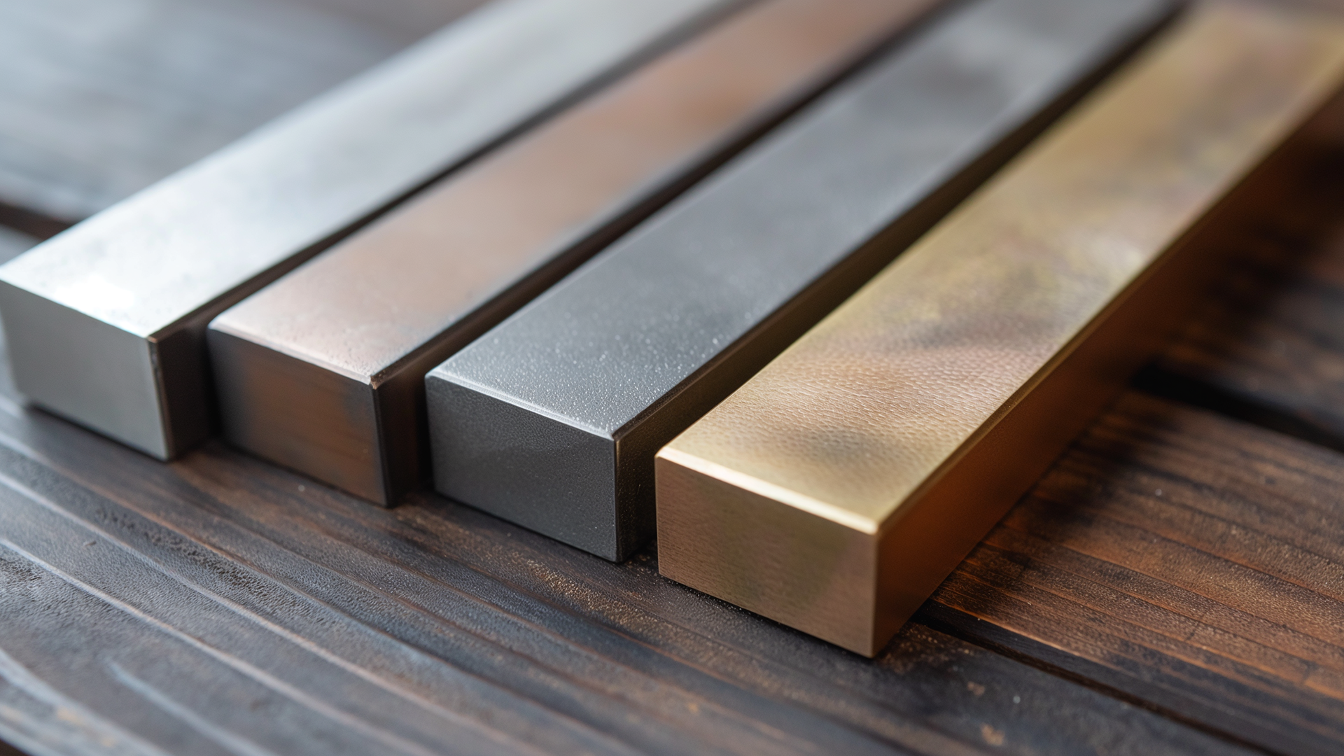
- Corrosion Resistance and Durability: Materials like ASTM A131 EH36 steel, commonly used in shipbuilding, are rigorously tested to confirm their ability to withstand saltwater exposure and mechanical loads. EH36 steel, for example, offers a tensile strength of 71,000 to 90,000 psi (490–620 MPa), which makes it an ideal material for ship hulls.
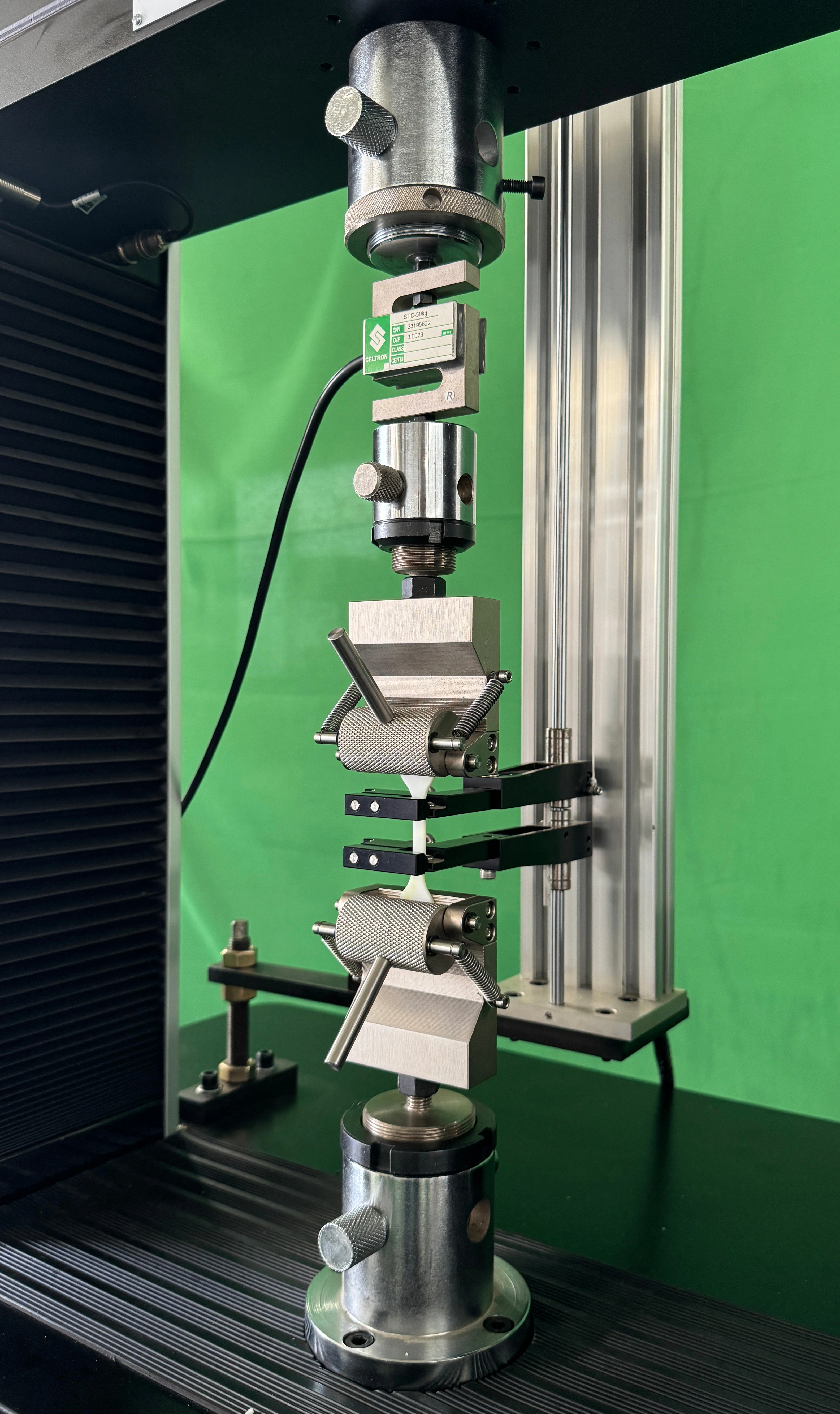
- Synthetic Materials for Ropes: High-strength synthetic fibers used in mooring ropes are subjected to tensile testing to confirm their ability to handle repeated stress cycles. These tests verify that ropes retain elasticity and strength under varying conditions, crucial for safe docking and anchoring.
2. Assuring Structural Integrity in Shipbuilding
Structural integrity is the core of maritime safety, and tensile testing helps prevent potential failures by guaranteeing that every component meets design specifications.
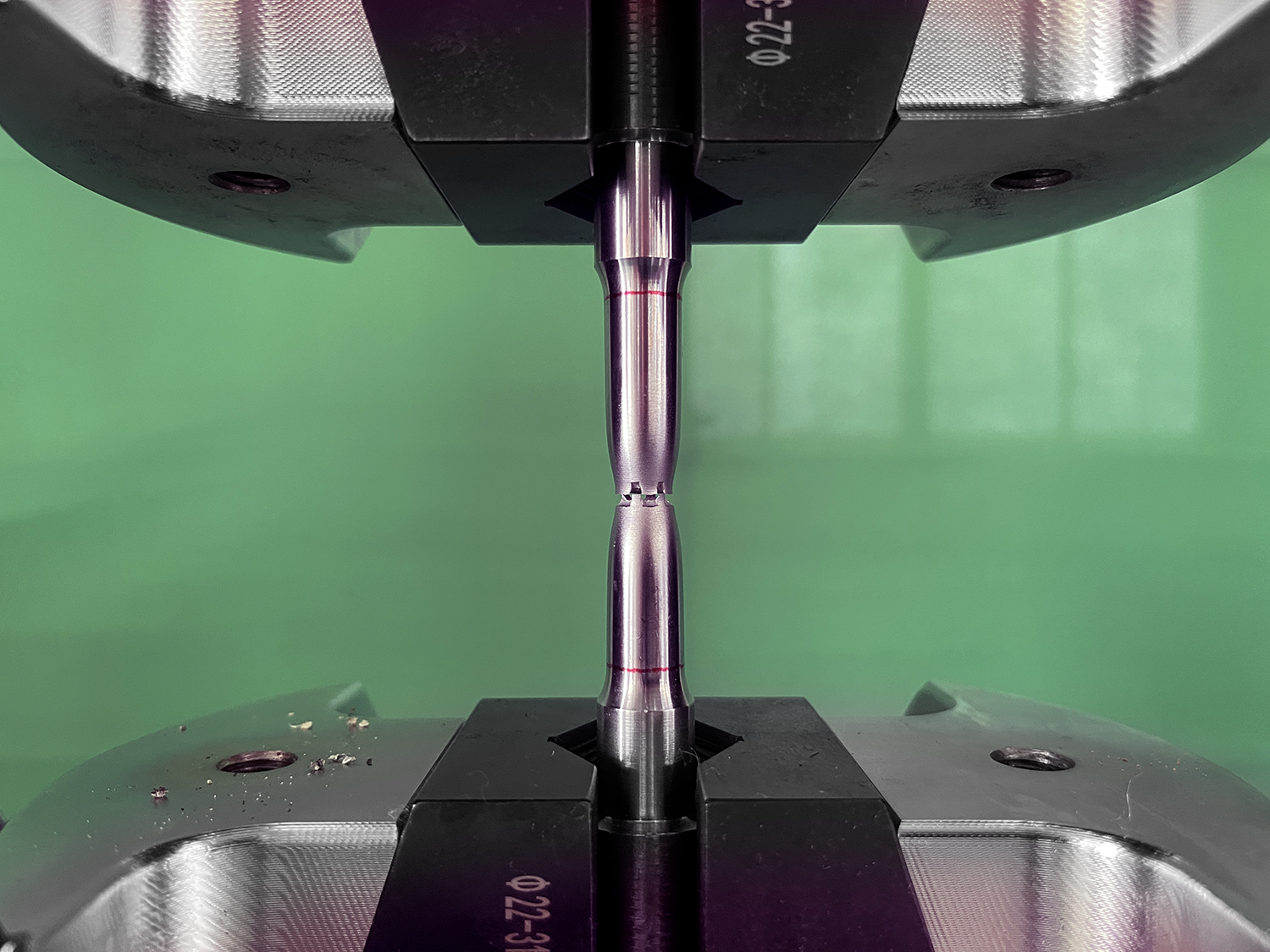
- Hull and Deck Construction: A tensile test evaluates the strength of welded joints, steel plates, and reinforcements used in shipbuilding. For instance, materials tested to American Bureau of Shipping (ABS) standards require a minimum tensile strength of 58,000 psi (400 MPa) to handle the stresses of cargo loads and wave impact.
- Real-World Example: During the construction of modern tankers, tensile testing confirms that steel frames can withstand the forces exerted by liquid cargo shifting at sea, preventing structural deformations.
3. Quality Assurance in Marine Equipment
Marine equipment reliability such as cables, chains, and connectors is critical to safe operations. Testing for tensile strength verifies that these components can endure the loads they are designed for.
- Testing of Wire Ropes: Mooring systems depend on wire ropes that maintain strength under extreme tension. Tensile tests confirm that these ropes meet safety requirements and operate reliably for extended periods.
- Compliance with Standards: Marine components are often tested to meet international standards, such as ISO 31000 for risk management in marine equipment, assuring long-term safety and operational efficiency.
The Indirect Benefits of Tensile Testing for the Marine Industry
Moreover, tensile testing also delivers a number of indirect advantages that enhance efficiency, reliability, and innovation in the marine industry. The following are 3 key indirect advantages that make tensile testing so worthwhile.
1. Cost Savings Through Preventive Measures
Testing for tensile strength helps identify potential weaknesses in materials and components before failure. This proactive approach reduces costly downtime and repairs. For instance, detecting early-stage fatigue in mooring ropes or structural components can prevent major accidents, saving millions in repair costs and operational delays.
2. Building Trust Among Stakeholders
In the highly regulated marine industry, demonstrating a commitment to safety and quality through tensile testing builds trust with stakeholders, including regulators, insurers, and customers. Equipment and vessels tested to stringent standards are more likely to gain approval for use in international waters, opening opportunities for global operations.
3. Supporting Innovation in Material Development
A tensile test is a crucial step in the development of advanced marine materials. By analyzing the performance of innovative materials such as composite polymers and high-strength alloys, tensile testing enables manufacturers to introduce lighter, stronger, and more corrosion-resistant solutions, leading to increased efficiency and sustainability in the industry.
Reliable Equipment for Accurate Tensile Testing Data
As a company specializing in tensile testing equipment, we understand the importance of reliable data. You have come to the right place if you are looking for a high-performance solution to evaluate materials and fasteners with precision and efficiency. Let us introduce our state-of-the-art Servo Hydraulic Universal Testing Machine 2000kN.
Servo Hydraulic Universal Testing Machine 2000kN: Advanced Features and Benefits
The Servo Hydraulic Universal Testing Machine 2000kN delivers exceptional accuracy and versatility for tensile, compression, and bending tests. This cutting-edge system is ideally suited for laboratories, quality control sectors, and industrial applications requiring rigorous material and fastener evaluation.
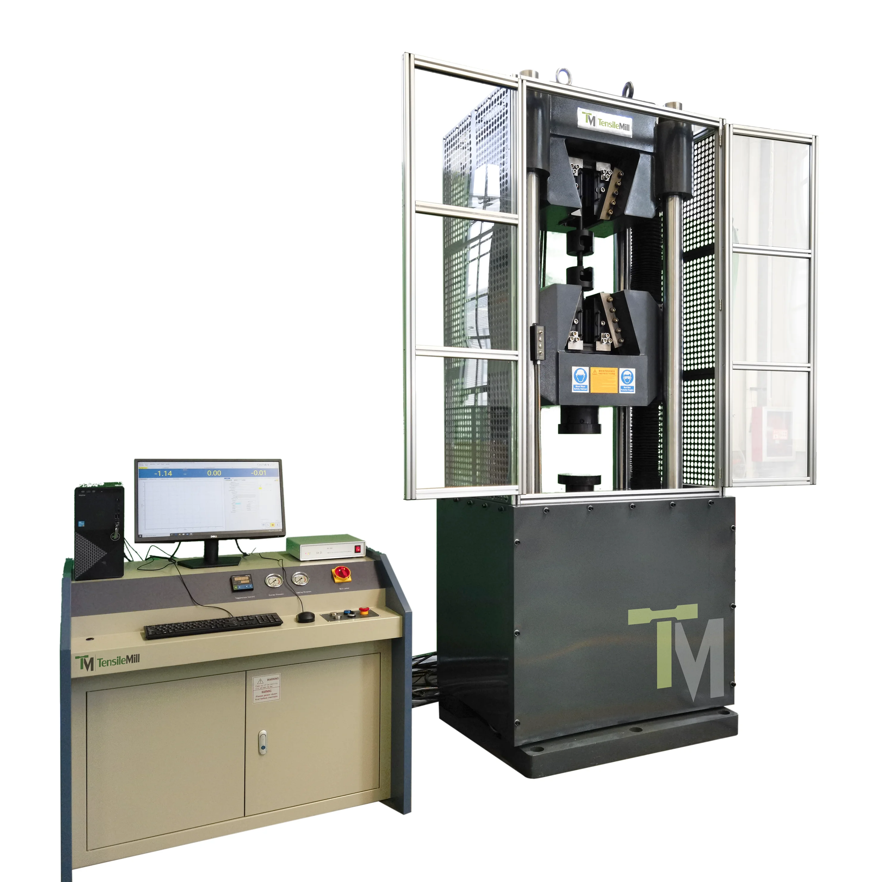
The machine has the following key features:
- Dual Testing Spaces: An upper space for tensile testing and a lower space for compression and bending tests provide flexible and efficient operations.
- Impressive Testing Force: With a maximum testing force of 2000 kN (449,617 lbf), the machine can handle even the most demanding testing requirements.
- Precise Measurement and Control: A high-accuracy load cell, photoelectric encoder, and three-closed loop control system (load, displacement, strain) guarantee maximum precision during tests.
- Specialized for Fasteners: Capable of testing bolts and nuts of grades 8.8, 10.9, and 12.9, with specifications ranging from M6 to M56, offering reliable assessments of high-strength fasteners.
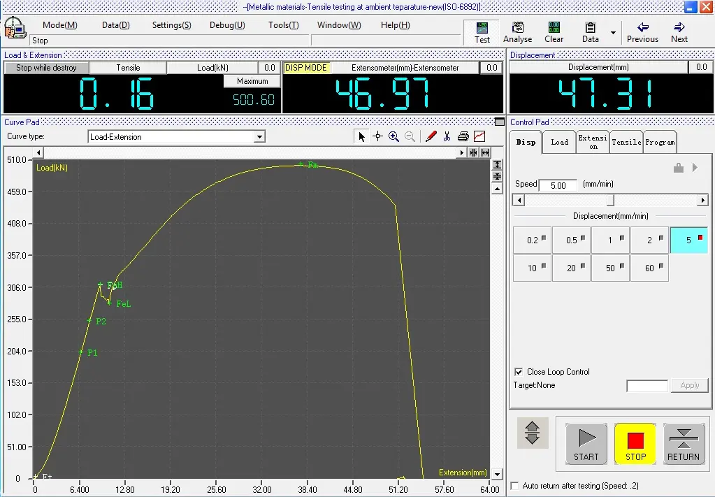
- Advanced Software Integration: The MaxTest software provides real-time monitoring, analysis, and multi-curve generation, enabling detailed insights into material behavior under various conditions.
Moreover, the hydraulic system is equipped with high-quality components, including an Italian ATOS servo valve and a Japanese NACHI oil pump. This guarantees long-term performance and durability. Innovative load frame design and non-slip tensile grip further increase operator convenience and accuracy.
Tensile Testing as the Backbone of Marine Safety
To summarize, it is important to recognize that the tensile test is more than just a technical process. It is the backbone of marine safety, reliability, and progress. When verifying that materials can withstand the harshest environments, tensile testing protects crew, cargo, and vessels from structural failures. A key role is played in material selection, structural integrity, and quality assurance, directly influencing the operational efficiency and long-term success of maritime enterprises.
On top of that, the indirect benefits of tension testing—such as cost savings, stakeholder trust, and material innovation—confirm its value as an indispensable practice for the marine industry. Through comprehensive testing, industries can meet international standards, improve performance, and achieve sustainability goals.
If you have any further questions, please do not hesitate to contact us or request a quote online.