If you’re familiar with tensile testing, you’ve probably come across a device called an extensometer. In simple terms, extensometers measure how much a material stretches under load. They track strain, giving engineers the data they need to calculate key properties like elastic modulus, yield point, and total elongation.
But how exactly do these instruments work? And what types of extensometers are available today? That’s what we’ll cover in this article.
We’ll go through:
- What extensometers are and what they measure
- How they work in real tensile testing setups
- The main types, from clip-on to laser-based models
- Pros, limitations, and how to choose the right one
Whether you run a materials lab or simply need reliable data from your tensile testing, this guide will walk you through the essentials — clearly and practically.
What Are Extensometers?
The word “extensometer” comes from “extension” and “meter.” It refers to a device that measures how much a material stretches, compresses, or shifts under mechanical load. In tensile testing, extensometers track how the length of a sample changes when it's pulled. This change is known as strain.
Unlike a testing machine's crosshead, which shows how far the grips have moved, an extensometer focuses only on the specimen. It isolates what’s happening inside the material. This helps engineers collect clean, focused data on how a sample deforms during the test.
Extensometers calculate strain by comparing the distance between two points on the specimen before and after loading. That distance is called the gauge length. The strain is simply the difference divided by the original length.
Strain data is key in nearly every standardized tensile test. Extensometers allow accurate calculation of elastic modulus, yield point, and total elongation. These values form the basis of product design, materials selection, and quality control.
You’ll find extensometers in labs testing metals, plastics, composites, rubbers, and even building materials. They are used in industries that rely on precise knowledge of how materials deform under load. Whether it's a small clip-on tool or a complex optical system, every extensometer has the same purpose: to measure how the material behaves under stress.
Why Strain Measurement Needs a Dedicated Instrument
Relying only on machine travel to calculate strain is not enough. That method includes movement from the test frame, grips, and other parts of the system. These extra shifts distort the real deformation happening inside the specimen.
An extensometer avoids this problem. It measures strain directly from the gauge section, not from the entire setup. That makes the results more accurate and repeatable.
Most testing standards, such as those from ASTM and ISO, require extensometers for good reason. Without one, fine elastic strains go undetected. Even a small error in early deformation can throw off values for elastic modulus or yield strength.
Modern extensometers can detect changes as small as a few micrometers. That’s essential when working with metals, ceramics, or other rigid materials where deformation happens quickly and in small amounts. Some extensometers are designed for large strains, especially in rubbers or soft plastics, where stretch continues for hundreds of percent before failure.

Why Extensometers Are Necessary in Tensile Testing
In tensile testing, extensometers provide the only reliable way to measure strain with high precision. Without them, engineers would rely on machine crosshead movement, which includes grip slippage, frame deflection, and other system artifacts. Extensometers measure the actual deformation happening in the specimen’s gauge section.
They are required for capturing critical properties such as elastic modulus, yield point, ultimate tensile strength, and total elongation. Most international standards, including ASTM E8 and ISO 6892, specifically call for extensometers when calculating modulus and offset yield values. These results depend on accurate detection of small elastic strains — sometimes as low as 0.1%.
Extensometers also enable measurements that crosshead displacement alone cannot provide. For example, they allow engineers to identify the 0.2% yield point, track the proportional limit, and monitor both uniform and localized necking until fracture. Dual-axis setups or optical systems using extensometry also make it possible to calculate Poisson’s ratio.
In day-to-day lab work, extensometers simplify the test process. They record elongation continuously and in real time, removing the need for manual measurements at multiple stages. Most devices feed data directly into software or test controllers. High-resolution models can detect length changes smaller than one micrometer, which is crucial for testing stiff materials like ceramics and hardened steels. Others are built to handle extremely large strains, such as 300% or more, for flexible materials like rubber or plastic films.
How Extensometers Work
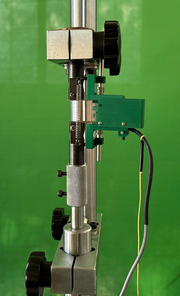
The core function of an extensometer is to measure how far two points on a specimen move apart or closer together when a load is applied. In contact models, the device physically attaches to the sample, usually at two sharp knife edges or fixed contact points spaced at a known gauge length. As the specimen stretches or compresses, the device senses the micro-displacement between these points and converts it into an electrical signal proportional to strain.
Two common sensing mechanisms are used: strain-gauge-based and inductive (LVDT). Strain-gauge extensometers have flexible arms that deform slightly as the sample elongates. This movement strains a sensor bridge, changing its electrical resistance. LVDT-based models use a coil and a moving core: as the extensometer's arms shift, the core moves inside the coil, altering inductance. Both systems can detect incredibly small displacements — often less than 0.000025 mm.
Some advanced extensometers use optical systems instead of mechanical contact. One example is a video extensometer. Before the test, technicians apply two visible markers (dots, lines) on the specimen’s surface at a fixed distance. A high-resolution camera records the test, and software tracks the distance between the markers in each frame. Knowing the pixel scale, the system calculates real-time strain without touching the specimen.
Laser extensometers go a step further. They measure surface deformation by analyzing laser light reflected from the specimen. These systems often don’t even need surface markings — the laser tracks natural texture shifts or interference patterns. High-end laser systems can achieve resolution better than 0.1 microns, while video extensometers often resolve down to 1 micron, meeting the most demanding ISO 9513 Class 0.5 accuracy standards.
Types of Extensometers
Extensometers are generally classified into two broad categories: contact and non-contact. Both types are used to measure strain in materials, but they differ in how they interact with the specimen and in which applications they perform best.
Contact Extensometers
These devices physically attach to the specimen, usually using sharp knife edges, spring-loaded clips, or lever arms. They are the traditional choice for standard tensile tests.
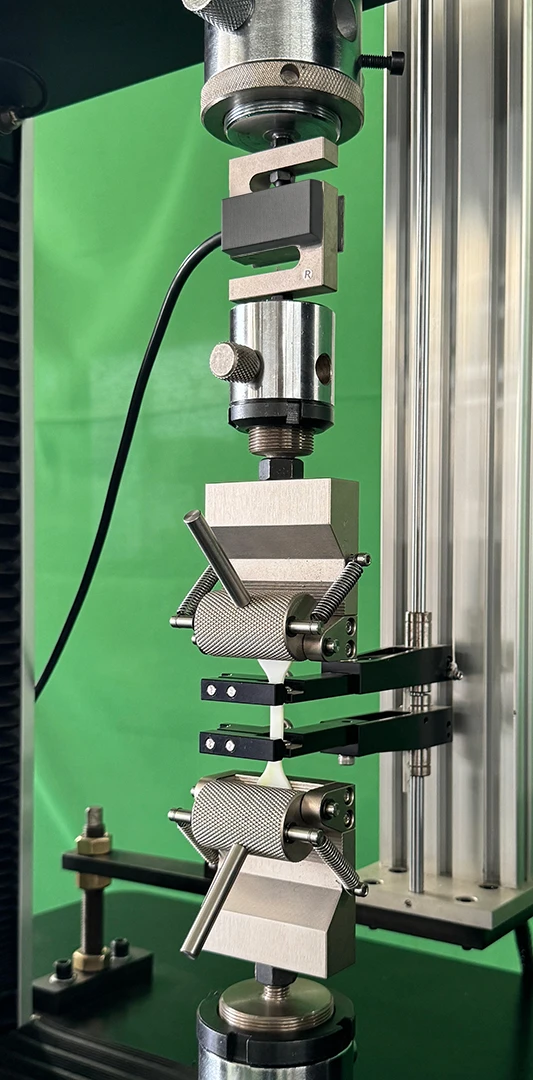
- Clip-On Extensometers: These are compact and manually mounted onto the specimen before testing. Held in place by spring force, they are widely used for measuring small strains, especially on metal samples under ASTM or ISO protocols. They are highly accurate, affordable, and available in various gauge lengths and measuring ranges. However, they are not ideal for fragile, thin, or highly elastic specimens due to the physical contact.
- Long-Travel Extensometers: Designed for materials with high elongation, such as rubbers, polymers, or films. These models can track extensions of up to 800–1000 mm. They usually rely on LVDT displacement sensors and feature extended arms or guide rails to follow the entire elongation range until break.
- Automatic Contact Extensometers: Also known as feeler-arm extensometers, these are motorized and fully integrated into the testing system. They can automatically position themselves before the test and retract afterward, minimizing operator influence. They offer high precision (up to 0.3 µm resolution), are robust enough to remain attached during break, and are suitable for high-throughput environments.
Non-Contact Extensometers
These systems measure strain without touching the specimen. They rely on optical methods such as video tracking or laser reflection.
- Video Extensometers: These use high-resolution cameras to track two markers applied to the specimen. They can measure axial and transverse strain simultaneously and are excellent for delicate samples or those that release high energy when they break. Advanced systems allow real-time observation of crack formation and plastic deformation.
- Laser Extensometers: Ideal for extreme environments such as high or low temperatures, where physical attachment is not possible. These systems use a laser beam and a sensor to calculate displacement, often without needing surface markers. They are especially useful in furnaces or cryo chambers.
While non-contact systems are typically more expensive and require careful calibration and lighting control, they eliminate the risk of influencing the test and are becoming more common in labs due to advances in camera technology and digital processing.
Contact vs. Non-Contact Extensometers: Pros and Cons
Contact Extensometers
Contact extensometers provide high precision when measuring small elastic strains, especially strain-gauge and LVDT models. They’re generally straightforward to use: attach the device to the specimen and begin testing. These systems tend to be more affordable than optical ones and are unaffected by external lighting or testing environments such as oil baths or submersion setups. Many models are built for durability — with overload protection, high-temperature extension arms, and compatibility with cyclic or extreme tests. They’re especially effective for testing stiff materials like metals, composites, and rigid plastics.
Their main drawback is physical interaction with the specimen. For soft or brittle materials, the added weight or pressure of a clip-on extensometer may distort results or cause early failure. They also have a limited travel range — once the gauge length exceeds this, the device must be removed to avoid damage, meaning late-stage strain data may be lost. Setup time can also be an issue: each specimen requires careful mounting. Additionally, testing at very high or low temperatures needs specialized contact devices or alternatives like optical systems.
Non-Contact Extensometers
Non-contact systems, such as video or laser extensometers, place no physical load on the specimen — ideal for delicate or reactive materials. They can measure deformation right up to and beyond fracture, capturing failure behavior in detail. These systems are invaluable in explosive or high-strain tests where contact sensors might be damaged. They’re also the only viable option for high-temperature testing (up to 1200°C) or environments where standard mounting isn't possible. Some video extensometers measure axial and transverse strain simultaneously, making them suitable for Poisson’s ratio determination or full-field analysis using digital image correlation (DIC). With no moving parts, optical systems require less maintenance over time.
Cost is the main barrier. Optical extensometers are significantly more expensive than basic clip-on models. They also require calibration, environmental control, and sometimes specimen preparation (like applying contrast markers). Lighting changes, vibrations, or obstructions can interfere with accuracy unless compensated by high-end filters and software. While resolution is often high, not all systems meet the sub-micron accuracy needed for measuring small strains over short gauge lengths. In such cases, contact extensometers remain preferable.
Applications and Use Cases
Extensometers are used wherever material deformation must be measured accurately. Their primary role is in tensile testing, whether of metal rods, plastic specimens, or composite panels, where they track elongation and help build precise stress–strain curves. But their scope goes beyond simple tension tests.
Extensometers are also used in:
- Compression testing: to measure how stiff materials like concrete or rock shorten under load.
- Bend testing: to track deflection in three-point or four-point flexural setups.
- Fatigue and cyclic testing: to monitor strain amplitude and detect fatigue behavior over repeated loading cycles.
- Creep and relaxation testing: to observe how materials deform over time under constant stress or strain.
- High-temperature testing: with ceramic-armed or non-contact extensometers operating through furnace windows up to 1000°C.
- Cryogenic testing: for materials exposed to sub-zero conditions.
- Underwater or pressure testing: in harsh environments like oil, saltwater, or sealed chambers.
Almost any material tested for mechanical properties can benefit from extensometry:
- Metals and alloys: to determine Young’s modulus, yield point, and ductility.
- Polymers and elastomers: to assess stiffness and large strain capacities.
- Composites: to measure strain to failure and interlaminar performance.
- Construction materials: like concrete, cement, and stone — especially in compression and flexural testing.
- Specialized materials: such as textiles, wood, paper, and thin films — often requiring non-contact extensometry.
Extensometers are essential in:
- Metallurgy: for sheet metal quality control.
- Aerospace: for selecting materials with precise stiffness and strength.
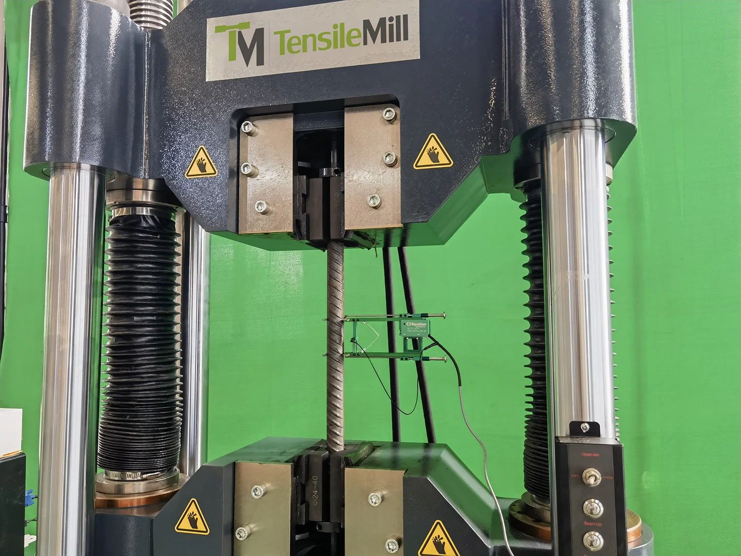
- Construction: for testing rebar, cables, and reinforcement materials.
- Oil and gas: for pipeline and structural evaluations.
- Polymer manufacturing: for certifying plastic performance.
In geotechnics, mining, and civil monitoring, extensometers take on broader roles:
- Geological displacement tracking: to monitor rock fractures, slope shifts, or underground settlement.
- Groundwater studies: to observe land subsidence from aquifer depletion.
- Structural monitoring: of bridges, dams, or buildings — using wire, laser, or anchor-based extensometers to detect structural movement.
Choosing the Right Extensometer Matters
Extensometers are essential in any serious material testing setup. Without them, accurate stress–strain curves, modulus calculations, and yield strength detection are simply not possible. Understanding the differences between contact and non-contact systems helps engineers select the right tool for the job — whether for metals, polymers, composites, or tests under extreme conditions.
At TensileMill CNC, extensometry is part of our core focus. We offer a range of extensometer options tailored to tensile testing needs, from high-precision clip-on units to flexible non-contact systems. If you’re looking for a solution that fits your lab or production environment, request a quote or contact us. We’ll help you choose the best match for your testing requirements.