
Did you know that spacecraft materials must withstand conditions far harsher than anything on Earth? From the intense vibrations during launch to the extreme temperatures of space, these materials face relentless challenges. Yet, one of the most fascinating aspects of space exploration is how materials behave in microgravity—an environment where conventional testing methods often fall short.
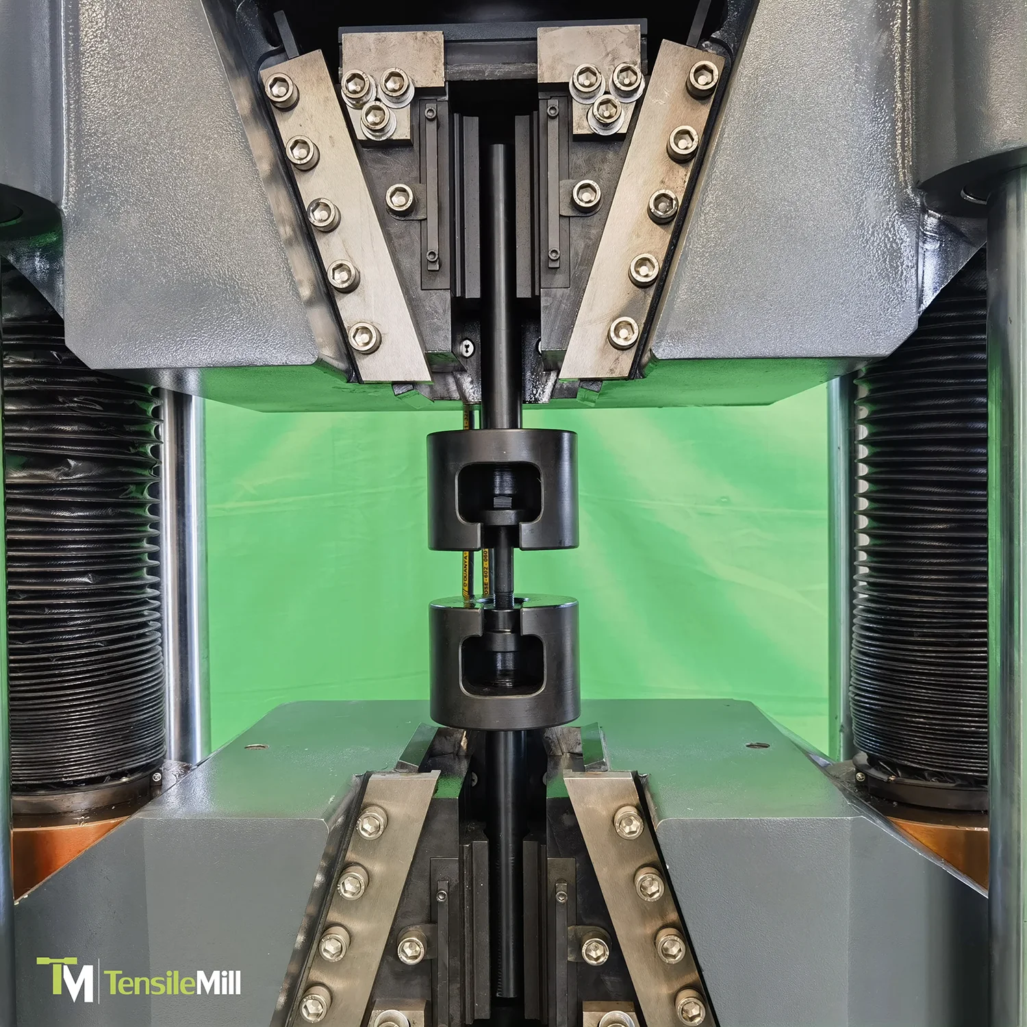
By stretching materials to their limits, tensile testing reveals key properties like strength, elasticity, and durability. These insights are necessary for developing spacecraft components that can withstand space travel stresses.
As space exploration advances, with missions venturing further and longer than ever before, the demand for reliable materials grows. Tensile testing not only provides safety and performance but also pushes the boundaries of material science, making humanity’s dreams of exploring the cosmos a reality.
Understanding Tensile Testing and Its Earthly Foundations
To better understand tensile testing’s key function in space exploration, we first need to appreciate its importance here on Earth and its importance in our daily lives. Tensile testing is a method used to evaluate materials' mechanical properties by stretching them to their breaking point. It provides vital information about a material's strength, ductility, and elasticity, helping engineers determine its suitability for different applications.
This testing method is an important tool in industries ranging from construction and automotive to consumer goods. For instance, skyscrapers undergo tensile testing to verify that they can support enormous loads without fracturing. Similarly, car tires are tested for tensile strength to guarantee safety under high-speed and high-pressure conditions. Even everyday objects like smartphone screens and sports equipment must meet rigorous tensile testing standards to guarantee their reliability and durability.
These evaluations are not just important—they are indispensable. By identifying weaknesses before materials are used, tensile testing prevents failures that could lead to costly repairs, accidents, or even loss of life.
Applications of Tensile Testing in Space Exploration
As humanity reaches for the stars, the materials used to build spacecraft, satellites, and space habitats must meet extraordinary demands. Tests of tensile strength are necessary to verify that these materials can endure space harsh realities, such as extreme temperatures, radiation, and prolonged stress in microgravity conditions.
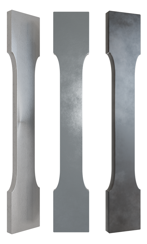
In space exploration, tensile testing is applied to evaluate lightweight alloys, composites, and advanced polymers—materials developed to minimize weight while maximizing strength. For example, titanium alloys used in spacecraft frames are tested to withstand the immense forces experienced during launch and the prolonged exposure to thermal cycles in orbit. Similarly, solar panels and shielding components undergo tensile tests to verify that they remain intact despite the stress of deployment and the bombardment of micrometeoroids.
One significant example is NASA’s testing of 3D-printed materials for in-orbit manufacturing. Tensile testing confirms that these innovative materials are strong enough to support critical structures, such as repair tools or satellite components, fabricated during missions. Another application is in reusable rockets, where tensile testing validates the durability of materials that undergo repeated use, including exposure to high-velocity re-entry forces.
Challenges of Material Testing in Microgravity
Conducting material testing in space introduces an entirely different set of challenges, particularly in microgravity environments where conventional testing methods often need adaptation. Microgravity alters materials' behavior, affecting stress distribution, thermal expansion, and structural stability. Understanding these differences is key to developing materials that can withstand space travel demands.
One major challenge is replicating microgravity conditions during testing. On Earth, engineers use specialized facilities like drop towers, parabolic flights, and centrifuges to simulate reduced gravity. These environments allow for short-duration tests, but the results must often be extrapolated to predict long-term behavior in true microgravity.
Thermal extremes in space also complicate testing. Materials must endure drastic temperature swings—from the scorching heat of direct sunlight to the freezing cold of shadowed regions. Tensile tests conducted in controlled environments can simulate these conditions, but testing materials in real orbital or deep-space settings offers more accurate insights.
Another difficulty lies in the transportation and use of testing equipment in space. Devices must be lightweight, durable, and autonomous to minimize astronaut intervention. For instance, tensile testing systems on the International Space Station (ISS) are compact and designed for precision in low-gravity environments.
Advances in Tensile Testing Technology for Space Exploration
As space missions become more ambitious, advancements in tensile testing technology are paving the way for better material performance and reliability in extraterrestrial environments. Modern innovations have transformed tensile testing, enabling precise evaluations both on Earth and in space.
One major advancement is the development of portable and automated tensile testing systems. These systems are compact, lightweight, and designed for microgravity. For example, equipment deployed on the ISS allows astronauts to test materials in real time, reducing the need to transport samples back to Earth for analysis. This capability is particularly useful for long-duration missions where immediate feedback on material performance is of primary importance.
Another breakthrough is the integration of in-situ testing technologies. These systems, used during spacecraft assembly and operations, monitor materials under actual space conditions, such as vacuum exposure, thermal fluctuations, and radiation. In-situ testing has proven invaluable for identifying potential weaknesses before they escalate into mission-critical failures.
Advances in 3D printing and additive manufacturing have also reshaped tensile testing. Materials produced in orbit—like repair tools or structural components—undergo tensile tests immediately after fabrication to ensure they meet performance standards. NASA’s work with 3D-printed polymers and metals has shown how these technologies can create reliable components, even in space challenges.
Looking ahead, the promise of tensile testing in space lies in AI-driven analysis and smart materials. AI systems can process test data rapidly, predicting material behavior under diverse conditions. Meanwhile, smart materials, capable of self-healing or adapting to stresses, will be subjected to comprehensive tensile testing to validate their effectiveness for next-generation spacecraft.

Innovative Solution for Tensile and Impact Specimen Preparation
As a company dedicated to advancing tensile testing technologies, we understand that reliable sample preparation is the foundation of accurate and repeatable test results. Alongside our high-tech tensile testing equipment, we also provide cutting-edge solutions for tensile and impact specimen preparation. One such solution is the TensileMill CNC - Classic Upgrade, an innovative machine built to meet the highest standards of precision and flexibility.
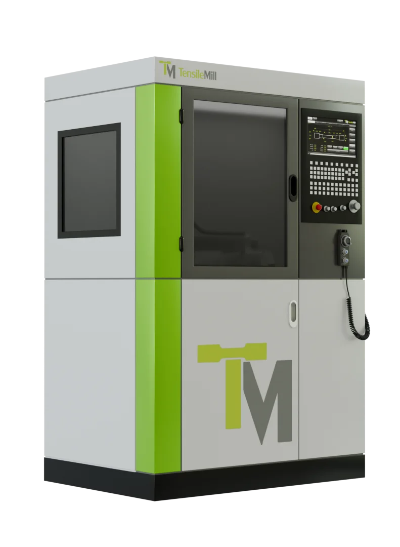
The TensileMill CNC - Classic Upgrade is not only ideal for traditional tensile and impact specimen preparation but also perfectly suited to industries exploring space materials. Its ability to produce specimens compliant with ASTM, ISO, DIN, and JIS standards guarantees readiness for even the most demanding tests. With this unit, engineers and scientists working on space projects can confidently prepare specimens that replicate space exploration conditions.
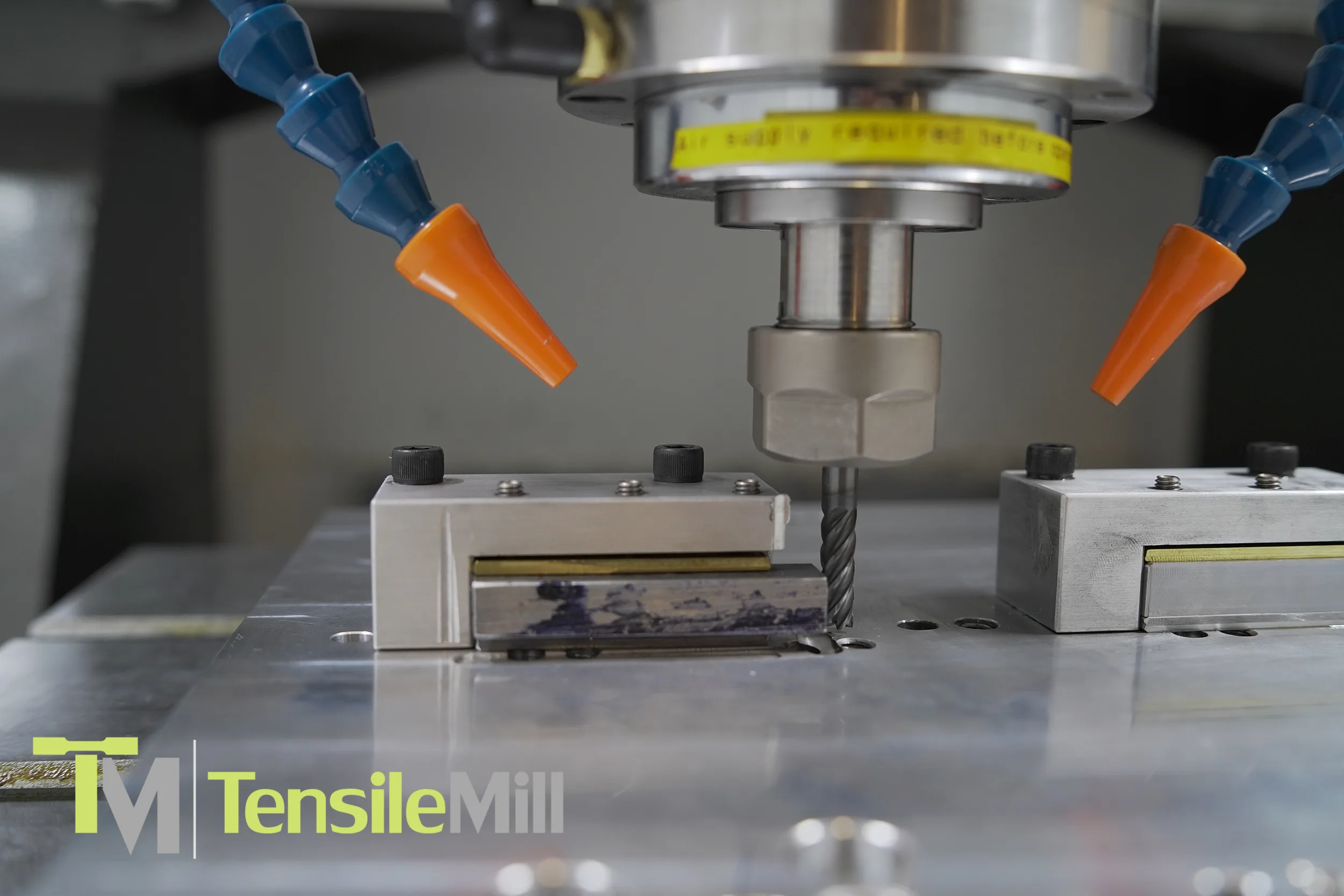
This machine offers exceptional accuracy and efficiency, capable of preparing specimens up to 14” (350mm) in length, 2” (50mm) in width, and 0.5” (12.5mm) in thickness. Equipped with a powerful 3.2kW servo motor, it achieves precision down to 0.0003”, ensuring consistent results every time. Whether working with lightweight alloys or advanced composites for spacecraft, the TensileMill CNC - Classic Upgrade simplifies the process with features like its user-friendly TensileSoft™ software, triple clamping fixture, and automatic lubrication system.
For space exploration, where material reliability is a must-have necessity, this hybrid system is a game-changer. Its ability to prepare both flat tensile and impact specimens makes it an ideal tool for projects requiring stringent compliance with ASTM E23 standards. By simplifying specimen preparation and delivering high-quality results, the TensileMill CNC - Classic Upgrade enables engineers to meet space exploration challenges with confidence and precision.
The Future of Material Testing: Bridging Earth and Space
Tensile testing remains a fundamental process in both everyday applications and the advanced frontiers of space exploration. From verifying the safety of structures and consumer products on Earth to validating spacecraft materials' performance in microgravity, this testing method underpins progress in numerous industries. It continues to evolve with cutting-edge advancements like in-situ testing, real-time evaluation, and AI-driven material analysis, preparing us for tomorrow's challenges.
As humanity reaches further into the cosmos, tensile testing will play an even greater role in guaranteeing materials' reliability and durability. By pushing the limits of what materials can achieve, tensile testing helps realize the dream of safe and sustainable space exploration.
If you are looking for high-quality tensile testing equipment and tensile sample preparation machines that can perform comprehensive procedures for different applications-including space exploration—TensileMill CNC has you covered. We offer a comprehensive range of equipment built to meet international standards, providing precision and reliability for all your testing needs. To learn more about our equipment or to ask a question, please contact us directly or request an online quote.