What is Heat Treatment?
Heat treatment (or heat treating) is a process in manufacturing that involves the controlled heating and cooling of materials, primarily metals and alloys, to modify their properties for specific applications. By precisely regulating temperature and cooling rates, heat treatment can significantly increase the material’s characteristics, such as increasing its hardness, strength, or toughness. This transformation is necessary to prepare the material for its intended use, making sure it can meet performance requirements in different applications. Though often overlooked, heat treatment has an important role to play in the material's life cycle, optimizing it for both functional and structural purposes in many fields.
The Process of Heat Treating Metals
Heat treatment involves three stages: heating, soaking, and cooling.
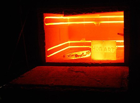
1. Heating Stage
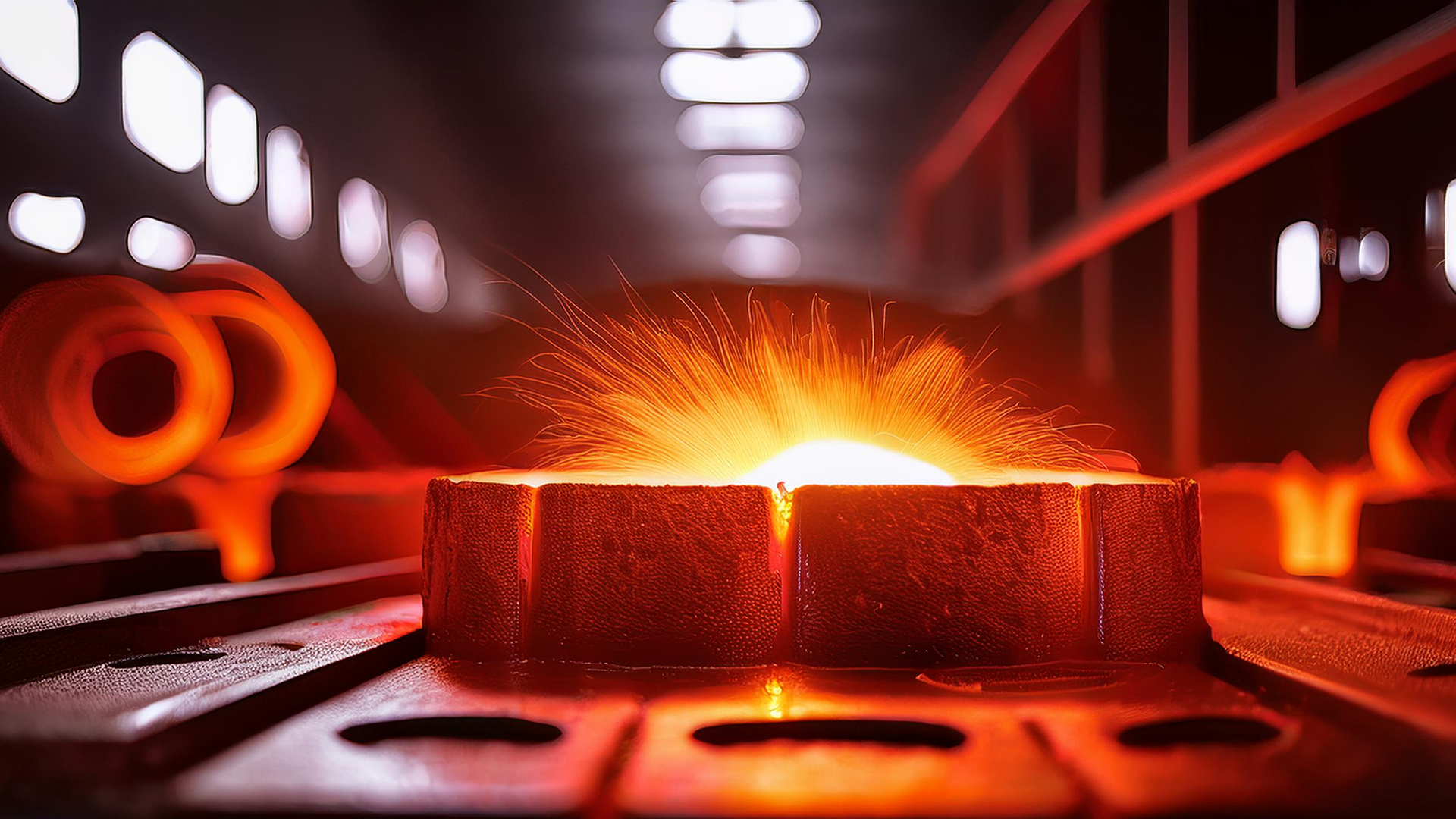
The metal is gradually heated to a specific temperature, resulting in uniform heating throughout the material. This is critical to avoid uneven expansion, which could lead to distortions or cracks. The rate of heating depends on factors such as the metal's conductivity, previous treatments, and the size and shape of the piece. For larger or irregularly shaped parts, slower heating is necessary to maintain consistency across the material.
2. Soaking Stage
Once the metal reaches the desired temperature, it is maintained at this level during the soaking stage. This allows the metal's internal structure to transition into a more stable phase, such as the austenitic phase in steel. During this phase, the crystal structure undergoes a reorganization. The soaking time is calculated based on the chemical composition and size of the metal so that even the thickest sections achieve the necessary structural changes.
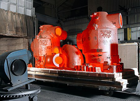
3. Cooling Stage
After soaking, the metal undergoes controlled cooling, which determines its final properties. The cooling medium—whether air, oil, water, or brine—affects the rate of cooling and, consequently, the material's hardness, strength, and ductility. For example, rapid cooling, or quenching, often results in a hard and brittle martensitic structure. In contrast, slower cooling leads to a softer, more ductile pearlitic structure. The choice of cooling method must be carefully matched to the type of metal and the desired outcome to prevent cracking or warping.
Internal Heat Treatment Processes
When metals undergo heat treatment, several critical physical processes alter their internal structure and, consequently, their mechanical properties. At the core of these changes is the manipulation of the metal’s microstructure, specifically the grains and the crystalline lattice within the material.
Phase Transformation
One of the primary processes during heat treatment is phase transformation. For instance, in steel, when the metal is heated to a high temperature, it enters a phase known as austenite, where the iron atoms are arranged in a face-centered cubic (FCC) structure. This phase is more open and allows carbon atoms to dissolve into iron more easily. However, as the metal cools, it can transition to different phases depending on the cooling rate and temperature. For example, slow cooling results in the formation of ferrite and cementite, creating a pearlitic structure that is relatively soft and ductile. On the other hand, rapid cooling or quenching traps carbon atoms within the structure, leading to the formation of martensite, a hard and brittle phase characterized by a body-centered tetragonal (BCT) structure.
Grain Structure and Size
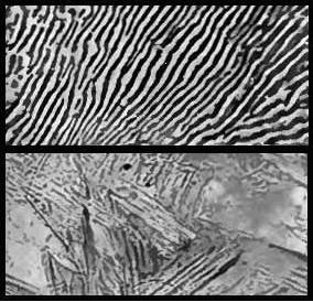
Heat treatment also affects the size and arrangement of grains within the metal. Grain size is crucial because it influences metal strength, toughness, and ductility. When a metal is heated above its recrystallization temperature, new grains form that are free of the dislocations and imperfections that weaken the material. If cooled slowly, the grains have time to grow larger, which generally results in a softer metal. Rapid cooling, however, results in smaller grains and a harder, more brittle material. This grain refinement process improves the metal’s mechanical properties, making it stronger and more resistant to fracture.
Diffusion and Precipitation
Another key process during heat treatment is diffusion, where atoms within the metal move and redistribute themselves, often leading to the formation of new phases. In alloys, this can lead to the precipitation of secondary phases at the grain boundaries, a process known as precipitation hardening. For example, in aluminum alloys, heat treatment can precipitate fine particles that block dislocation movement, increasing alloy strength.
Allotropic Transformations
In certain metals, such as iron, heat treatment can cause allotropic transformations, where the metal changes its crystal structure based on temperature. For instance, iron can exist in several different forms, including alpha (ferrite), gamma (austenite), and delta iron, depending on temperature. These transformations significantly affect the metal’s properties, as different crystal structures have varying capacities for dissolving carbon and other alloying elements.
Overview of Heat Treatment Techniques
Listed below are some of the most common heat treatment techniques, including annealing, normalizing, hardening, tempering, and selective heat treating.
Annealing
Annealing is a heat treatment process used to increase metal ductility and reduce hardness, making it easier to work with. This process involves heating the metal to a specific temperature, depending on its composition, and then allowing it to cool slowly. The slow cooling allows the metal’s internal structure to rearrange itself, relieving internal stresses and creating a refined microstructure. This process is particularly useful for metals that have been work-hardened during machining or shaping, as it softens the material, making it more malleable for further processing.
In ferrous alloys like steel, annealing typically involves heating the metal beyond its upper critical temperature, followed by slow cooling. This results in pearlite, a softer and more ductile microstructure. For non-ferrous metals, annealing removes hardness induced by cold working, making them easier to shape and machine. Different types of annealing, such as full annealing, process annealing, and recrystallization annealing, are used depending on the specific requirements of the metal and its intended application.
Normalizing
Normalizing is a heat treatment process used to uniformize alloy grain size and composition, especially in ferrous metals. Unlike annealing, normalizing involves cooling the metal in open air after heating it to a temperature slightly above its upper critical temperature. This cooling process is faster than annealing, leading to a more refined and uniform grain structure.
Normalizing is used to eliminate irregularities in the microstructure that can occur during casting, welding, or other manufacturing processes. By normalizing, the metal achieves a more consistent hardness and strength throughout, making it more suitable for further processing or final use. Normalized steel typically has higher hardness and strength compared to fully annealed steel but is less ductile, which can be beneficial depending on the intended application.
Hardening
Hardening is a heat treatment process designed to increase metal hardness and strength. This process involves heating the metal to a high temperature, followed by rapid cooling or quenching. Rapid cooling traps the metal’s microstructure in a high-energy state, resulting in a hard but often brittle material.
The most common hardening method involves quenching steel in water, oil, or another cooling medium after heating it above its upper critical temperature. This process produces martensite, a hard and brittle microstructure that significantly increases metal hardness. However, because hardening can make metal brittle, tempering is often followed to reduce brittleness while maintaining hardness.
Tempering
Tempering is a secondary heat treatment process typically performed after hardening to reduce the brittleness of the metal while maintaining most of its hardness. In this process, the hardened metal is reheated to a temperature lower than the original hardening temperature and then allowed to cool slowly. This reheating allows the microstructure to relax slightly, reducing internal stresses and increasing toughness.
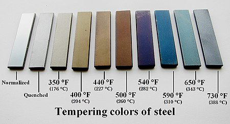
The tempering temperature determines the final balance between hardness and ductility. For example, lower tempering temperatures retain more hardness, making the metal suitable for cutting tools, while higher tempering temperatures increase ductility, making the metal more suitable for applications requiring resilience and toughness, such as springs or structural components.
Selective Heat Treating
Selective heat treatment involves applying heat treatment to only specific areas of a metal object to achieve different properties in different regions. Techniques such as differential hardening, flame hardening, and induction hardening allow certain parts of an object to be hardened while leaving other areas softer. This is particularly useful in tools and weapons, where a hard edge is needed for cutting or striking, but the rest of the tool must remain tough and resilient.
Heat Treating in Material Testing
Materials that have been heat-treated undergo laboratory testing in order to assess their characteristics under specific conditions. With the help of annealing, quenching, or tempering, metals achieve specific properties that are then evaluated to verify that they meet the necessary standards for their intended applications. Tests of heat-treated samples are essential to confirm that the materials possess the strength, hardness, and durability required to perform reliably in demanding environments. As a result of this verification process, materials can be confidently used in critical applications, such as those in aerospace, automotive, and construction.
The Role of Reliable Equipment in Testing Applications
When heat-treated samples are tested, the accuracy and reliability of the results are heavily dependent on the quality of the testing equipment. It is imperative that the samples are measured accurately and evaluated for their mechanical properties, such as hardness, tensile strength, and ductility, using reliable equipment.
It is possible for the results to be significantly skewed if the equipment used is faulty or not properly calibrated. Incorrect measurements may, for example, result in an overestimation of a material's strength, resulting in the application of the material in a high-stress environment where it ultimately fails, leading to catastrophic consequences. In contrast, underestimating a material's properties could result in it being rejected when it is actually suitable, resulting in unnecessary expenditures and delays.
The use of advanced testing equipment, such as Universal Testing Machines (UTMs) and hardness testers, is specifically designed to handle the demands of testing heat-treated metals.
TM-SHM2000 Class A - Servo-Hydraulic Universal Testing Machine
As a business with many years of experience in supplying high-tech equipment for material testing, particularly tensile testing, we understand the critical importance of reliable test outcomes and the role that quality equipment holds in achieving them. If you are looking for a modern universal testing machine to evaluate everything from simple metals to heat-treated alloys, let us present you with our TM-SHM2000 Class A - Servo-Hydraulic Universal Testing Machine.
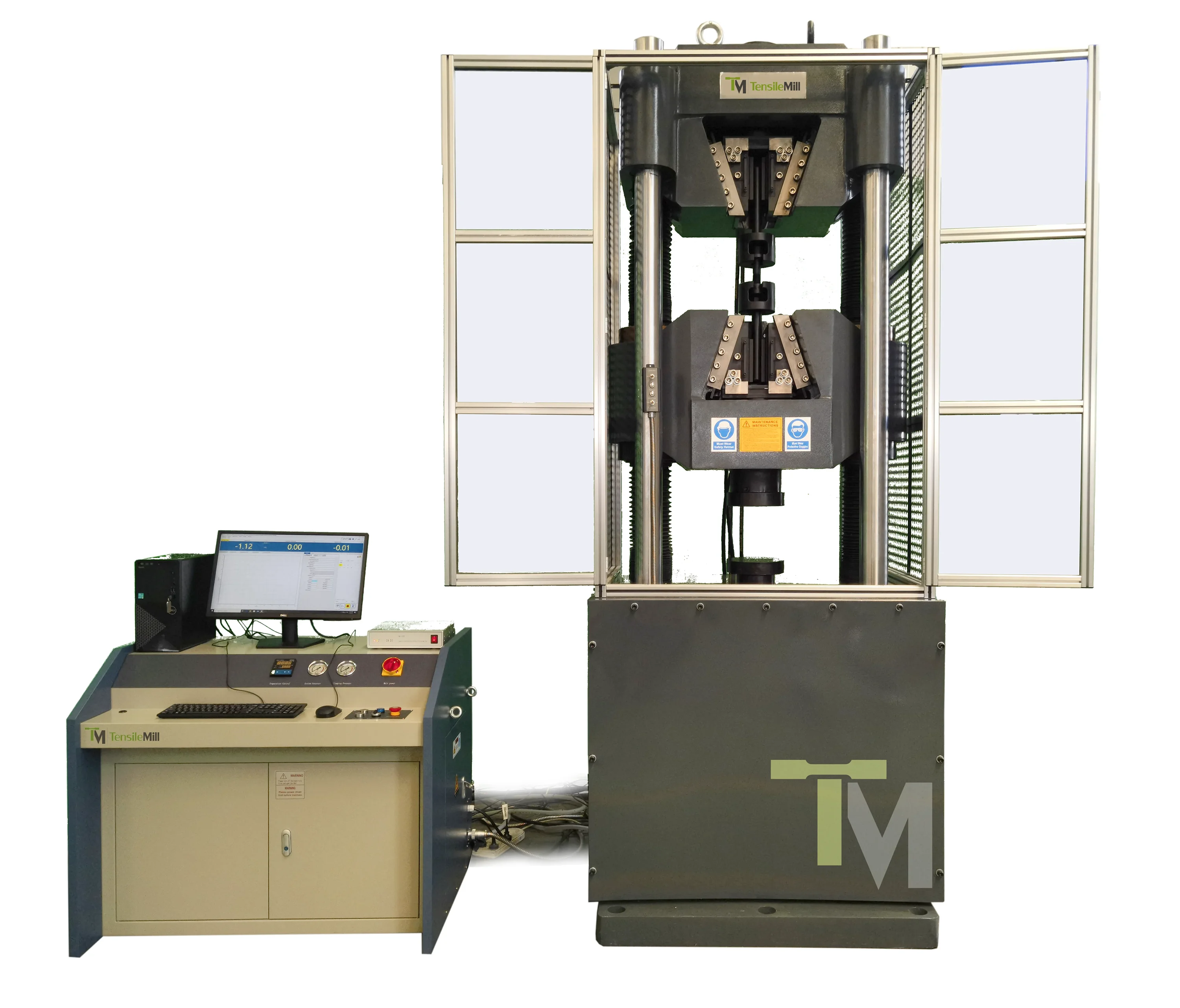
The TM-SHM2000 Class A is engineered to provide precise and reliable testing results. This machine handles a maximum testing force of 2000 kN, making it ideal for testing the tensile strength, compression, and bending of an array of materials, including bolts and fasteners.
Key features of the TM-SHM2000 Class A include its robust structure with four columns and two leading screws, resulting in exceptional stability and durability during testing. The machine has a hydraulic-operated tensile grip and a high-precision load cell, which allows for accurate force measurement—crucial for verifying heat-treated materials' mechanical properties. Additionally, it complies with international standards such as ASTM E4 and ISO 7500-1, guaranteeing that it meets the rigorous requirements needed for reliable material testing.
This UTM offers two distinct testing spaces: an upper space for tensile tests and a lower space for compression and bending tests, allowing for flexible testing capabilities. The precision Italian ATOS servo valve hydraulic power pack, along with a photoelectric encoder for displacement measurement, assures that the TM-SHM2000 Class A delivers consistent and accurate results regardless of the type of testing applications.
Mastering Heat Treatment for Optimal Material Performance
Heat treatment is a key component in the manufacturing and material science industries, having a significant impact on increasing the properties of metals and alloys for many types of applications. By precisely controlling the processes of heating, soaking, and cooling, engineers can tailor materials' mechanical properties, making them harder, stronger, or more ductile. Understanding the intricate details of these processes—from phase transformations to grain refinement—is essential for optimizing material performance in demanding environments.
Heat treatment techniques like annealing, normalizing, hardening, and tempering each offer distinct benefits, allowing materials to be customized for specific applications. The verification of these treated materials through rigorous testing confirms that they meet the stringent standards required for their intended use, guaranteeing safety and reliability.
You can learn more about our extensive line of equipment like CNC machines for making flat and round tensile specimens and universal testing machines for testing an array of materials, including heat-treated metals. Also, if you have questions or want to learn more about our tools, please do not hesitate to request an online quote or contact us directly. Allow us to assist you in any way we can.