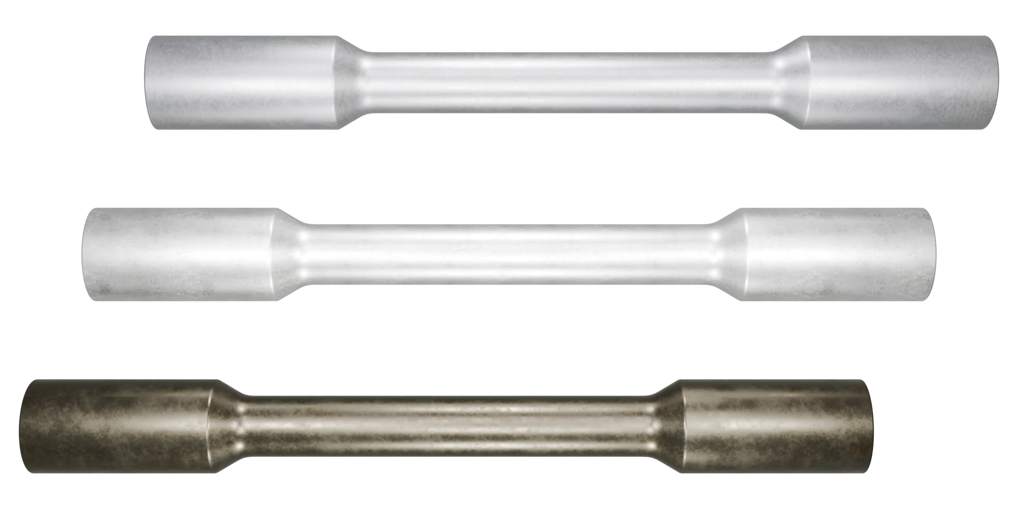
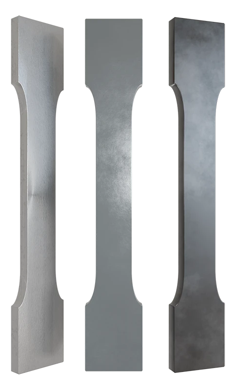
Have you ever seen a tensile test specimen? Those smooth, carefully shaped metal pieces—often round like a “dog bone” or flat like a metal coupon—look ready for testing right after machining. It may seem that their surface is already perfect. But in many cases, that is not enough.
In most material testing applications, these specimens must be polished to near perfection—completely free from scratches, burrs, or any surface defects. At first, this step may appear optional. After all, if the sample is already machined to shape, what is the point of polishing?
This is a common misunderstanding. Sample polishing is not just a final touch. It is key for the reliability and accuracy of tensile test results. Even the smallest surface flaw can lead to early failure or incorrect measurements.
If you want to understand why polishing matters, what problems can happen if it is skipped, how international standards like ASTM E8 and ISO 6892 address this step, and what equipment is used to polish specimens properly—this article is for you.
What Is Tensile Specimen Polishing?
Tensile specimen polishing is the process of enhancing the surface quality of a test specimen by carefully removing all visible and hidden imperfections—such as scratches, machining marks, burrs, and rough edges—before performing a tensile test. Although these imperfections may appear insignificant, they may greatly impact the material's behavior during testing.
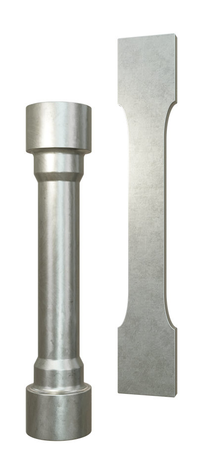
Polishing is usually applied to the gauge section of the specimen—the central part where the actual stretching and breaking will take place. It is also crucial for the edges, particularly when the specimen is cut from sheet metal. The goal is to generate a uniform and smooth surface that is devoid of any elements that could potentially compromise the material or distort the test results.
Why is this necessary? Poor sample preparation is the reason for over 60% of all tensile testing errors. Surface flaws can function as stress concentrators, resulting in the formation of weak points that may cause the material to fracture or break earlier than expected. This leads to incorrect measurements of tensile strength, yield strength, or elongation.
Polishing is even more critical for materials with high strength or low ductility. These materials are more susceptible to surface imperfections, and even a minor scratch can result in discrepancies between specimens. This scatter is mitigated by a well-polished specimen, which results in more consistent and dependable outcomes.
There is an additional significant rationale for polishing: to guarantee that the specimen breaks within the gauge length correctly. Tensile specimens are designed to fail in the center, away from the grips. However, the specimen may break at that point if there is a rough spot or sharp edge in another location. That makes the test invalid. Polishing reduces these weak points and facilitates the test's compliance with the appropriate fracture path.
The tensile specimen is sometimes created through punching or cutting, particularly for flat specimens. These methods can leave cold-worked zones and burrs. If not removed, these damaged areas can lead to lower strength and elongation results. The true performance of the material can be revealed by removing these defects with a light grinding or polishing step following the cutting process.
Why Polishing Tensile Test Specimens Is So Important
As previously mentioned, even minor deviations from the intended test conditions can result in misleading results in tensile testing. Surface quality is a frequently overlooked factor that affects the distribution of stress throughout the specimen during loading, in addition to the location of the failure.
Local concentrations can result in unexpected mechanical responses due to the uneven stress flow that unpolished areas can induce. For instance, engineers may incorrectly classify materials that typically exhibit ductile behavior due to surface flaws that result in brittle-like fractures.
Polishing is also beneficial when assessing sensitive material parameters, such as uniform elongation, necking behavior, or localized strain distribution, particularly when employing extensometers or digital image correlation (DIC) systems. In order to accurately monitor deformation, these optical methods necessitate a surface that is both clean and consistent. Distorted strain maps or false readings may result from any irregularities or burrs that may interfere with the measurement process.
Additionally, a smooth, reflective surface can help detect early-stage cracks during post-test analysis or fractography. When failure analysis is necessary, polished specimens exhibit more pronounced crack origins and propagation patterns when examined under a microscope. This is particularly helpful in the context of quality assurance protocols or failure investigations.
Consistent polishing practices also guarantee that specimens satisfy internal test standards or customer specifications from a quality control perspective. Polished surfaces increase the reliability of statistical analysis by reducing variability across test runs in laboratories that conduct repeated batch testing.
Lastly, polishing is required for regulatory and audit compliance. In sectors such as aerospace or defense, the test data may be rejected if surface preparation requirements are not met, even if the results appear to be appropriate. Internal procedures and external certifications often involve maintaining right surface quality.
Methods for Polishing Tensile Specimens
Different laboratories use different polishing methods based on test volume, material type, and consistency requirements. Some of the most common methodologies are as follows:
Manual Polishing
Manual polishing is often used in low-volume labs. It involves sanding the gauge section with abrasive papers of increasing grit. The process focuses on removing surface defects while keeping the scratches aligned with the loading direction. This reduces the risk of cracks forming across the specimen width. Although time-consuming, this method can produce reliable results when performed with care.
Semi-Automated Machines
Polishing machines designed for metallographic preparation can also be used for tensile specimens. These systems typically feature a rotating disc or belt where abrasive media are applied. They are suited for flat samples and allow for quicker and more consistent polishing than manual methods. Operators must monitor pressure and temperature to avoid altering the specimen's surface or shape.
Longitudinal Polishing Systems
Automated longitudinal polishers are the most effective solution for high volumes and strict surface quality. These systems prevent transverse scratches and produce uniform results by moving the abrasive along the specimen's length. They are optimal for fatigue-sensitive applications and routine production testing due to their ability to support multiple grit levels, controlled pressure, and repeatable settings.
Electropolishing
Electropolishing is used when mechanical grinding must be avoided. It removes surface irregularities through an electrochemical process without adding stress or heat. Although rarely used in routine tensile testing, it is advantageous for corrosion tests or high-purity materials in which the surface condition is important.
Standards and Best Practices for Specimen Surface Finish
The surface condition of tensile specimens is a clearly defined requirement in most international testing standards. These standards highlight the necessity of removing surface defects before testing in order to preserve safety, repeatability, and accuracy.
The most widely followed standard for tensile testing of metals in North America is ASTM E8/E8M. It specifically advises that inadequate specimen preparation is the primary cause for many test failures. The gauge section, which is the central portion of the specimen on which the test is conducted, must be free of any visible defects, as stipulated by the standard. This covers burrs, grooves, notches, and any rough or overheated areas.
Inaccurate results may result if these defects persist, as they can influence the material's behavior under load.
Additionally, ASTM E8 underlines that the impact of surface finish is even more obvious when testing materials with exceptionally high strength or low ductility. A small defect can have a substantial impact on the outcome of these materials. In such instances, the standard suggests that polishing or fine grinding be implemented to guarantee that the testing conditions are suitable. Polishing is not optional for sensitive metals; it is necessary to obtain valid results, as indicated by additional notes in the ASTM guidelines.
Global standards exhibit comparable expectations. ISO 6892-1, which is regularly used in Europe and on a global scale, provides instructions on specimen preparation and explicitly specifies polishing as an acceptable technique. The objective remains consistent: to attain accurate dimensions and a clean surface that has no impact on the material's behavior during testing.
DIN 50125, which is usually used along with ISO 6892, specifies that the surface roughness of a machined specimen should not exceed Ra 6.3 μm. This level of finish can often be unachievable through machining alone, which is why a light post-polishing step is often integrated into the preparation process.
Polishing is not only a good practice, but also a formal requirement in industries that are highly regulated, such as aerospace. The National Aerospace and Defense Contractors Accreditation Program (NADCAP) conducts audits of testing laboratories to verify that all preparation procedures comply with stringent regulations. One of the key checks in these audits is how the lab performs surface preparation, especially when testing critical parts made from aircraft-grade alloys. NADCAP recognizes special categories like “Low Stress Grinding” and “Low Stress Grinding and Polishing,” which are required to avoid introducing damage or heat during specimen preparation.
Reliable CNC Polishing System for Tensile Sample Preparation
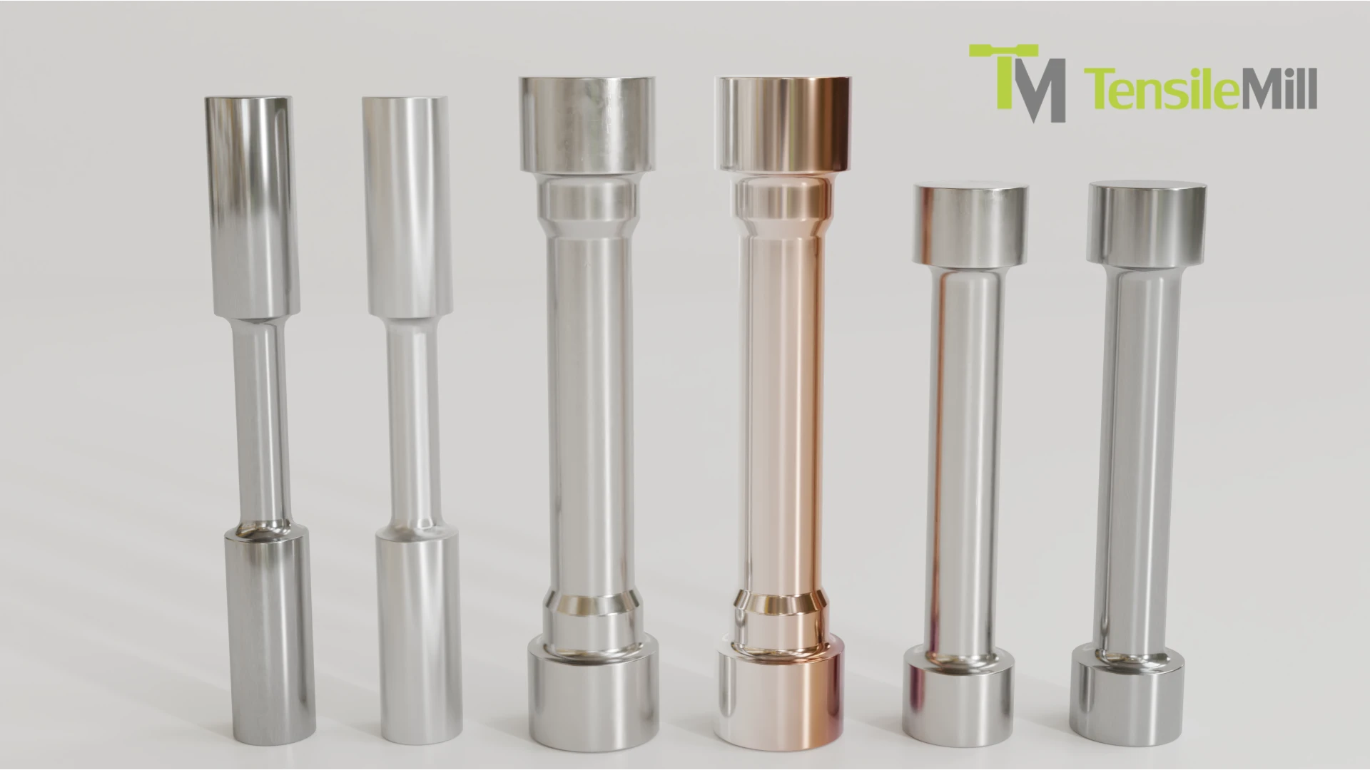
At TensileMill CNC, we provide reliable equipment for the entire tensile testing process, including universal testing systems, CNC sample preparation machines, and sample polishing solutions. If your lab requires precise, repeatable results, and compliance with international testing standards, we are proud to introduce our automated polishing system designed for professional and high-volume environments.
Automatic Longitudinal Polisher System – TensilePolish
The TensilePolish Automatic Longitudinal Polisher System has been developed to achieve a high-quality finish on both flat and cylindrical specimens. It is designed to minimize surface residual stress and grinding stress following machining processes, including milling and turning. The system guarantees consistent, repeatable surface preparation with minimal operator involvement, thanks to its customizable settings and intuitive touchscreen controls.

The specimen is polished automatically along its length using a controlled longitudinal motion. The system enables the precise adjustment of polishing parameters, such as the active polishing length (5–280 mm), sandpaper speed (10–100 mm/sec), specimen rotation (5–50 N), and polishing force (5–50 N). In order to optimize workflow efficiency, it can automatically transition between four distinct sandpaper grades during a single polishing cycle.
TensilePolish supports an extensive range of specimen types and sizes. Specialized fixtures are used to handle both cylindrical and flat geometries. Standard, small, and large cylindrical models, as well as standard flat specimen formats, are all available. Additionally, laboratories with distinctive polishing requirements may obtain a model that is completely customizable.
This system is suitable for aerospace, automotive, and fatigue-critical applications, as it meets the requirements of ASTM E466, ASTM E606, EN 6072, and NADCAP. The core polishing system, hardware for various geometries, a set of sandpaper rolls, and a comprehensive user manual with instructional videos are all included in each unit for a fast and effortless setup.
Final Notes on Tensile Specimen Polishing
The polishing of tensile specimens is not merely a surface-level detail. It is key to guaranteeing the precision and dependability of tensile testing results. Despite the fact that specimens may appear to be well-machined, the material's response to stress may be greatly affected by minor surface imperfections, such as scratches or burrs. Especially when testing high-strength or low-ductility materials, these imperfections may result in early fracture, distorted elongation readings, or invalid test outcomes.
Proper polishing is needed for the repeatability of tests and the accuracy of measurements. It assists in the consistent maintenance of failure locations within the gauge section and facilitates the dependable operation of optical tracking systems and extensometers. Furthermore, smooth surfaces are necessary for conducting quality assurance checks or failure analysis, as they simplify post-test evaluations.
The choice of polishing method is contingent upon many factors, such as the type of specimen, the capacity of the laboratory, and the level of precision that is required. Labs have an array of options to achieve the surface finish necessary to meet industry standards, including automated longitudinal systems, electropolishing, and manual techniques.
In environments that are regulated, polishing is mandatory. Proper specimen preparation is highlighted in international standards such as DIN 50125, ISO 6892, and ASTM E8. In industries such as aerospace, it is imperative to satisfy these surface requirements in order to pass audits, comply with NADCAP protocols, and preserve the credibility of the overall test.
TensileMill CNC is available to assist you in your search for polishing equipment or tensile testing systems that can help with any phase of your testing process. For personalized assistance and the optimal solution to your laboratory requirements, please reach out to us directly or submit an online quote.