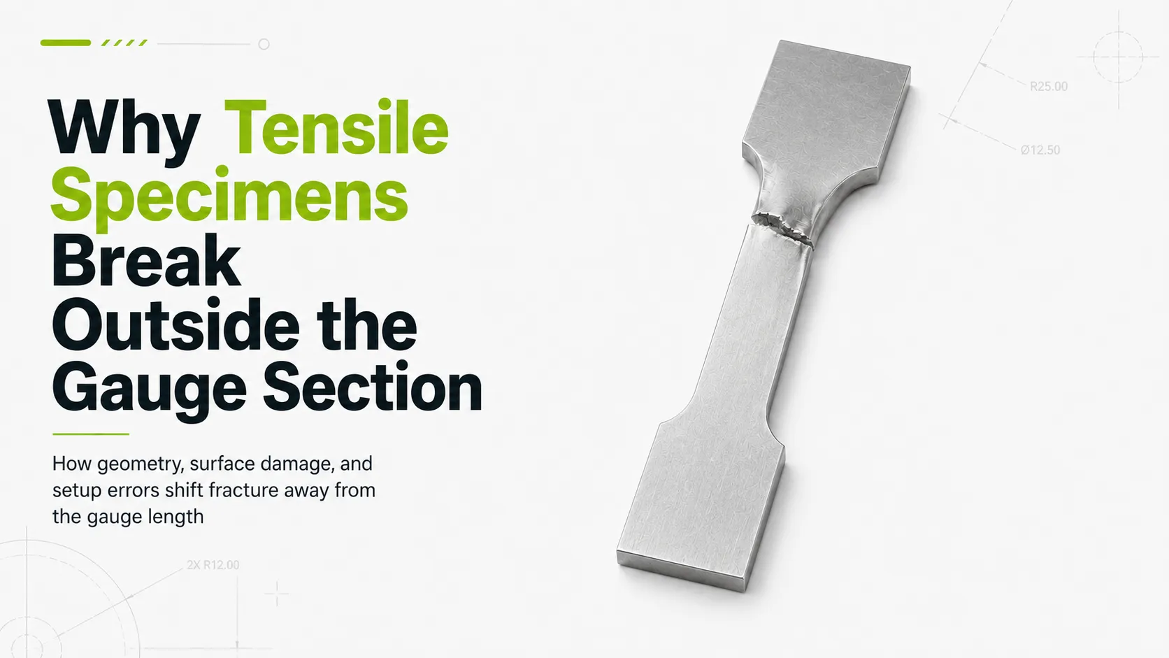
A tensile specimen that breaks at the shoulder or near the grip transition needs a preparation review before the material is judged. The fracture location may point to weak material, poor geometry, surface damage, or loading setup.
The reduced section is supposed to carry the main strain. If another area becomes the weak point, the lab should check specimen geometry before treating the tensile value as a clean material result. Shoulder radius, gauge width, taper, edge burrs, surface scratches, grip marks, and misalignment can all change where stress collects during the pull.
This problem shows up in both flat and round specimens. A flat sample may carry a burr along the reduced edge or an uneven shoulder cut. A round sample may have diameter drift, tool marks, or poor centering along the gauge length. Labs that prepare both types often use flat and round tensile sample preparation machines to keep those variables under control before testing.
Standards set the test method. Specimen preparation determines whether the sample enters that method with controlled geometry, clean transitions, and measurable dimensions.
The Gauge Section Is Designed To Control Where Failure Happens
A tensile specimen is shaped to control where deformation and fracture occur. The reduced section is there to place the highest working stress in a known area. That area is the gauge section, where elongation is measured and where the main fracture is expected to occur during a clean test.
The grip sections provide the clamping area needed to transfer load into the specimen. Between the grip area and the reduced section, the shoulder transition has to carry load smoothly into the gauge length. If that transition is too sharp, uneven, scratched, or poorly machined, it can become a second high-stress location.
In a well-prepared specimen, the smaller cross-section in the gauge area should draw the main deformation. The design gives the lab a controlled place to measure strain and review fracture behavior. ASTM E8/E8M uses tensile specimens to report properties such as yield strength, tensile strength, elongation, and reduction of area. Those numbers depend on the specimen loading cleanly through the intended section.
Problems begin when a notch, burr, scratch, taper, or sharp radius creates a higher local stress point than the intended gauge section. A burr near the shoulder can behave like a notch. A local scratch can start a fracture before the gauge area reaches its expected strain. Taper can move the highest stress toward one end of the reduced section. Poor radius control can pull the fracture into the shoulder.
A break near the grip, shoulder, or transition area does not automatically tell the lab that the material result is unusable. It does mean the fracture location needs context. The lab should look at the specimen geometry, machining marks, deburring method, surface condition, grip seating, and alignment before treating the result as normal material behavior.
Geometry Errors Can Move Stress Away From The Gauge Section
Specimen geometry sets the stress path. The reduced section is supposed to carry the highest tensile stress because it has the smallest planned cross-section. When another point becomes smaller, sharper, rougher, or offset from the loading axis, fracture may move away from the gauge section.
Shoulder radius is one of the first areas to check. A smooth radius lets load move from the grip section into the reduced section without a sharp stress jump. A tight radius, tool mark, cutter step, or uneven blend near the shoulder creates a local high-stress point. In flat specimens, the problem may appear on one edge only. In round specimens, the same issue may appear as a rough fillet or off-center transition.
Taper is another common cause. If width or diameter changes along the reduced section, the smallest cross-section becomes the likely break point. The same applies to local width drift after machining, uneven blank seating, or asymmetry between the left and right sides of a flat specimen. Poor centering in round specimens adds a separate risk because the specimen axis may not match the loading axis.
|
Problem |
What It Changes |
What The Lab Should Check |
|
Sharp Shoulder Radius |
Creates a local stress concentration near the transition |
Radius shape, cutter path, template or CNC program |
|
Tapered Gauge Section |
Moves highest stress toward the smaller cross-section |
Width or diameter at several points |
|
Burrs Near The Reduced Section |
Acts like a notch at the edge |
Edge condition, deburring method, magnified inspection |
|
Flat Specimen Asymmetry |
Loads one side differently than the other |
Left/right geometry, blank seating, fixture position |
|
Poor Round Specimen Centering |
Adds eccentric loading or uneven stress distribution |
TIR, center drilling, chucking, live center support |
|
Surface Scratches Near The Shoulder |
Creates a local fracture starter |
Scratch direction, polishing, handling marks |
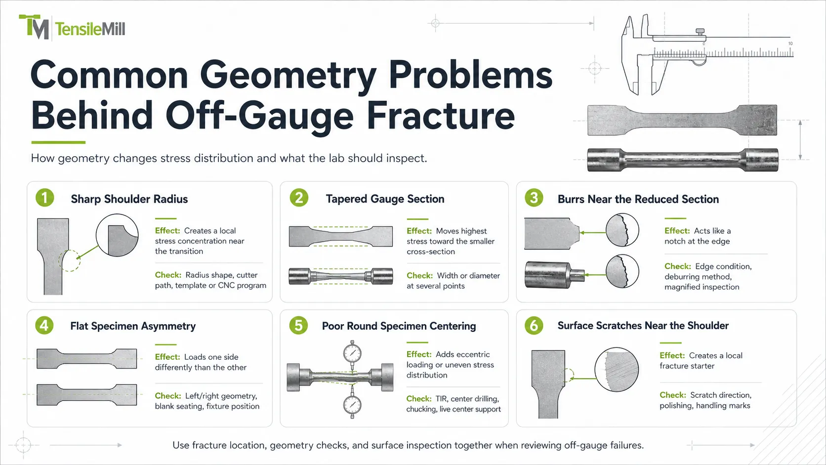
Off-gauge fracture often starts with specimen geometry. A sharp shoulder radius, taper, burr, scratch, or local width change can create a stronger stress point than the intended gauge section. Before the material is judged, the lab should check whether the prepared sample still matches the required shape.
Flat Specimens Often Fail From Edge And Shoulder Problems
Flat specimens expose two machined edges through the reduced section. Any edge defect in that area sits close to the highest-stress section of the sample. Burrs, rolled edges, scratches, chatter, or uneven deburring can create a weak point before the specimen reaches the frame.
Gauge width needs to be checked along the reduced section, not only at one point. A small local narrowing can pull the fracture toward that spot. Shoulder radius also needs a left/right comparison. If one side has a sharper transition, the specimen may not load symmetrically.
Blank support affects the finished edge. If the blank lifts, vibrates, or sits on chips during machining, the cutter may leave chatter, taper, or a stepped transition. Heat near the reduced edge can add another variable, especially in thin samples or materials that react poorly to aggressive cutting.
Flat tensile specimen preparation works best when geometry checks and surface review happen before the sample reaches the frame. Useful checks include CMM or template verification, 10x visual edge inspection, and light deburring that does not change the gauge width.
Round Specimens Add Centering, Runout, And Taper Risks
Round specimens fail from a different set of preparation problems. The gauge section is controlled by diameter, concentricity, straightness, surface finish, and the transition into the shoulders. A small diameter change along the gauge length changes the local cross-section. A poorly centered specimen adds eccentric loading before the tensile frame begins the pull.
Turning quality matters across the full gauge length. Tool marks, taper, out-of-round stock, chatter, or a rough fillet can shift fracture toward a local defect. Excess stickout during turning can add vibration. Poor chucking can move the centerline. A shoulder that looks smooth from one angle may still carry a tool step or surface mark that becomes visible after fracture.
Good round tensile specimen preparation starts before the finishing pass. Both ends should be faced and center-drilled. A tailstock live center helps support the part during cutting. Total indicated runout should be checked before machining, with a practical target at or below 0.001 in / 0.025 mm. After cutting, the lab should check the finished diameter along the gauge section and inspect the fillet radii.
Surface finish also needs a defined target. Many round tensile specimens use a smooth machined finish around 32-63 microinches Ra. Harder alloys, fatigue-sensitive work, or customer-specific methods may call for tighter control. The fracture should not start from a turning mark, diameter drift, or off-center transition introduced during preparation.
Machining Damage Can Turn Preparation Into A Test Variable
Machining damage often looks minor before testing. A small burr, transverse scratch, chatter line, or heat mark may not change the overall specimen shape. It can still create the first fracture point under tensile load.
Burrs near the reduced section behave like small notches. Transverse scratches cut across the loading direction. Chatter marks show unstable cutting or weak support. Heat discoloration may point to aggressive cutting, poor chip evacuation, dull tooling, or unsuitable coolant control. Aggressive deburring can create a second problem by changing the edge or reducing local width.
Surface condition should be reviewed together with the stress-strain curve. If the curve looks unusual and the fracture moved outside the gauge section, the failed specimen needs a physical inspection before the result is assigned to material behavior.
Check for:
- Burrs along the reduced section
- Scratches near the shoulder transition
- Chatter marks from unstable machining
- Heat discoloration near the machined edge
- Uneven deburring on one side of a flat specimen
- Diameter drift along a round gauge section
- Surface marks running across the loading direction
- Tool wear records or missing cutter history
Tool condition belongs in the same review. A dull cutter may leave a rougher edge, higher burrs, or heat marks. A worn collet may add runout. A dirty fixture can lift the blank enough to create taper. Those details are easier to find when the lab records the cutter, fixture, program, material lot, and deburring method used for each specimen group.
Alignment And Grip Effects Can Pull The Fracture Toward The Ends
Off-gauge fracture can also come from the test setup. A specimen may be machined correctly and still load poorly if its axis does not match the direction of applied force. Misalignment adds bending stress to a test that is supposed to apply tensile load along the specimen centerline.
ASTM E1012 is used for alignment verification because bending strain from off-axis loading can affect tensile and compressive test results. In practical lab terms, the specimen should sit straight, the grips should close evenly, and the load train should pull through the intended axis. Any offset pushes extra stress toward one side of the specimen.
Grip seating is a common source of trouble. Flat specimens can sit unevenly if the grip faces are dirty, worn, or mismatched. Round specimens can load off-center if the ends, threads, shoulders, or adapters do not seat correctly. Too much grip pressure can mark softer materials. Too little pressure can allow slip. Both conditions can move fracture toward the grip transition.
Grip marks need context. A clean break inside the reduced section is usually easier to read. A break near the shoulder, inside the grip, or just outside the clamped area needs a setup review. The lab should check specimen seating, jaw condition, clamping pressure, adapter alignment, and signs of slip.
Round specimens add another setup check. The prepared centerline and the test centerline should match as closely as possible. A well-turned gauge section loses value if the specimen is pulled through an eccentric adapter or seated against damaged threads.
Fracture near the grip transition should send the review in two directions: back to the specimen geometry and forward to the loading setup.
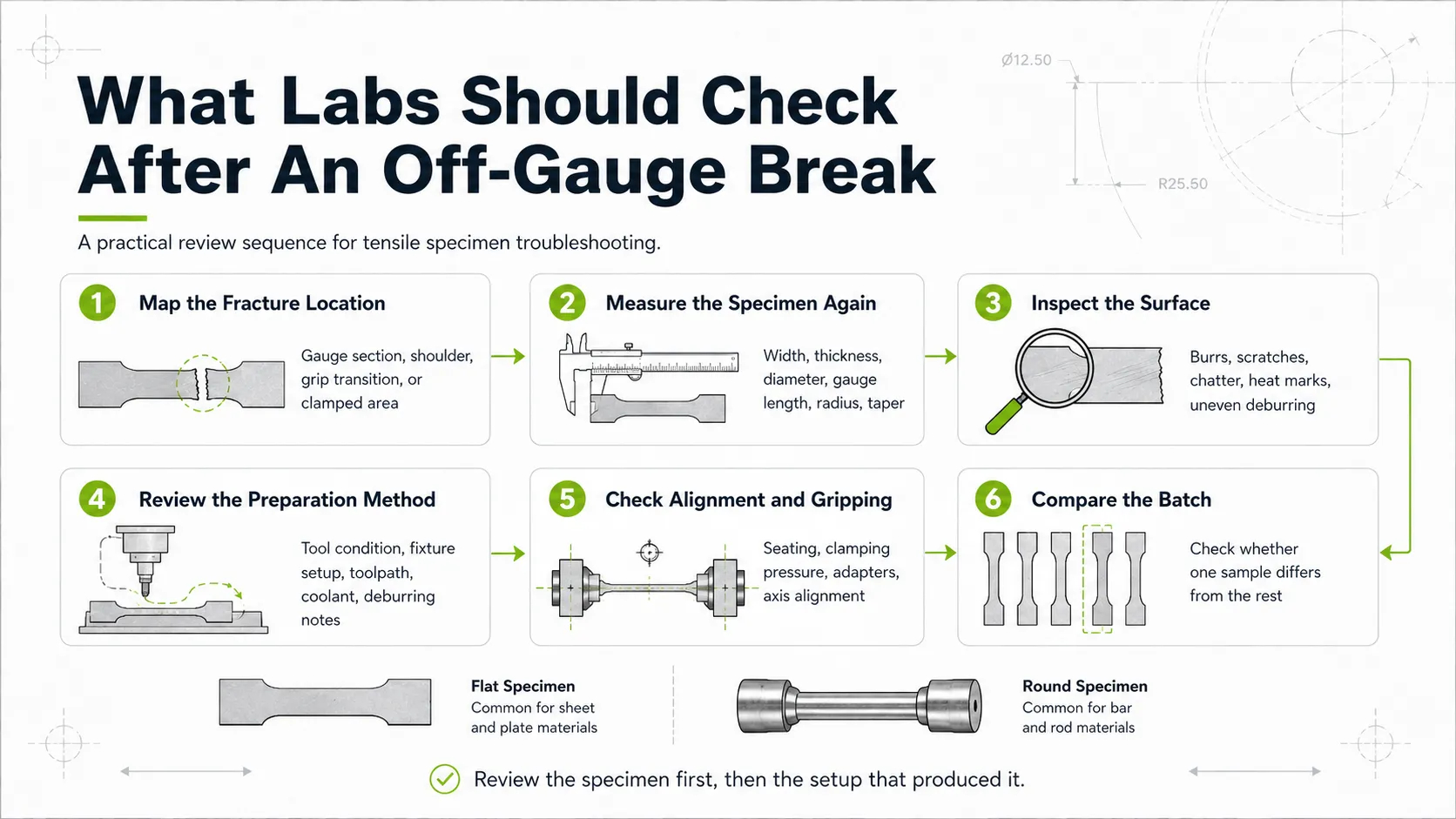
What Labs Should Check After An Off-Gauge Break
An off-gauge break should start with a review of the failed specimen. The fracture location may point to weak material, but it can also come from a machining mark, grip problem, taper, burr, or geometry error already present in the sample.
A useful review moves from the specimen outward to the setup that produced it.
- Map the fracture location
Record where the specimen broke. Separate gauge-section breaks from shoulder breaks, grip-transition breaks, and breaks inside the clamped area. A photo helps if the result needs to be discussed with production, a customer, or another lab. - Measure the specimen again
Check width, thickness, diameter, gauge length, shoulder radius, and taper. For flat specimens, measure more than one point along the reduced section. For round specimens, check diameter along the gauge length rather than relying on one center measurement. - Inspect the surface
Look for burrs, scratches, chatter, heat marks, and uneven deburring. Pay close attention to the side where fracture started. A small transverse scratch near the shoulder can matter more than a polished area far from the break. - Review the preparation method
Check cutter condition, fixture setup, toolpath, coolant, blank seating, and deburring notes. A change in tool wear, fixture cleanliness, or cutting parameters can explain a fracture shift better than the tensile curve alone. - Check round specimen alignment
Review TIR, center drilling, chucking method, live center support, finished diameter, and fillet condition. A round specimen with diameter drift or poor centering can pull unevenly even when the surface looks acceptable. - Review the test setup
Check grip faces, seating, clamping pressure, adapters, and alignment records. Look for slip marks or local grip damage. If the specimen was not seated on the intended axis, the test may have added bending stress to the tensile load. - Compare with the rest of the batch
If one specimen broke outside the gauge section, compare it with the other samples from the same batch. Check whether it had the same geometry, surface finish, tool record, preparation date, and failure location. A single off-gauge break may point to one damaged sample. A pattern across several samples may point to the preparation process or test setup.
After this review, the lab can decide whether to repeat the test, hold the result, inspect the remaining samples, or release the batch record with a note on fracture location.
Off-Gauge Fracture Should Start A Preparation Review
A tensile specimen that breaks outside the gauge section needs a preparation and setup review. The material may have failed under load, but the sample may also have carried a preparation defect into the frame.
The review starts with the prepared geometry. Gauge width, diameter, shoulder radius, taper, edge quality, and surface finish determine where stress collects during the pull. The next check is the setup. Grip seating, clamping pressure, adapters, and alignment can move stress toward the ends even when the specimen was machined correctly.
Good tensile data starts before the test begins. The specimen needs controlled geometry, clean transitions, measured dimensions, stable fixturing, and alignment through the load train. ASTM E8/E8M or ISO 6892-1 methods define the test framework. Specimen preparation decides whether the sample enters that framework in a condition that can produce defensible data.
If off-gauge breaks appear across several batches, the preparation workflow should be reviewed together with the test setup. TensileMill CNC systems cover flat and round tensile sample preparation for labs that need controlled geometry, repeatable machining, and equipment options for different specimen types. To match a machine to the material, specimen shape, standard, and expected sample volume, request a quote from the TensileMill CNC team.